CVS Digital Single Use Camcorder Hack
![]()
CVS Digital Single Use Camcorder: After the software and hardware hack on this camcorder, it becomes a regular, many-use digital camcorder. Resolution is defaul at 320x240, but that can be tweaked up to 640x480, and various other resolutions. It has 128Mb of built in memory, and its default time limit is 20 minutes. You can set that time limit to anything you want, the actual time limit being whatever the internal memory can hold. At the default resolution, that means at least 45 minutes. At higher resolution, the recording time goes down. The hack is very similar to the Dakota single use digital camera. The camera and comcorder use the same connectors in fact. I have added USB connectors to several of these camcorders for my use and friends' use. Take a look here http://camerahacks.10.forumer.com/ for full details on the connections to be made and the free software to download movies from the camcorder. There are several software versions available; the earlier ones are all hackable, the newest has yet to be hacked. The only problem is you won't know until you buy the camcorder and perform a Vulcan neck pinch on it: hold down Record and Delete while you turn it on and the software version will display on the LCD. Most camcorders sold now at CVS all have the newest software version. You need to find old stock or buy a older version on eBay.
|
I wanted to power this thing externally, so I would not need to carry the
2 AA batteries. Fortunately, this camcorder was very accomodating. The hacked
connector includes the four USB pinouts: data+, data-, common, power 5V. By
connecting the common and 5V lines directly to my receiver, I was able to remove the AA
batteries. I had also wanted to add Mr.RC-Cam's camera switch to this setup, but the
camcorder was not so accomodating in this respect. Most power and shutter switches
on digital cameras are activated by momentarily driving the connection to ground or Vcc.
This camcorder does neither of those. Each switch is an independent circuit.
While this could be adapted to electronically close the contacts by using optical
isolation for each siwtch, I decided to just go with the manual switches. I turn the
camcorder on and push "Record" at the beginning of a flight. With standard
resolution, I can record many flights in a single session, even switching between planes
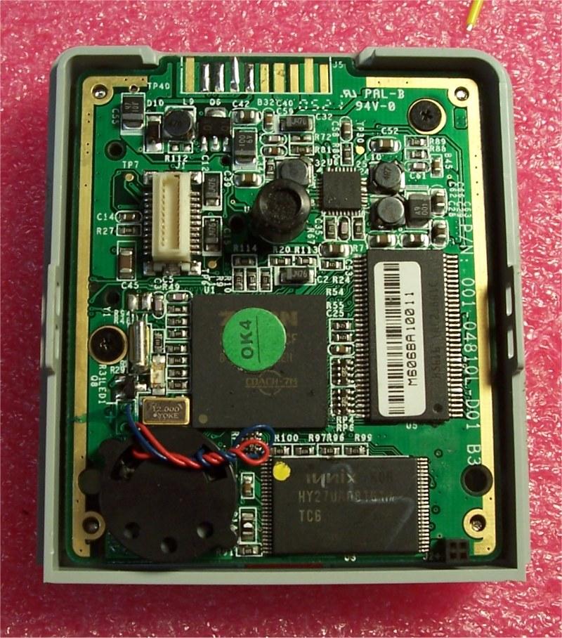
if I want to. This photo shows the front of the main board with the imager daughterboard removed. It normally plugs into the connector at the upper left. The battery compartment has also been cut off. The 10 pin connector at the top is the built in connector. You will need to make a plug to connect to that, or solder your own USB connector to pins 6, 7, 8, 9. Pin 1 is to the right, next to the label J5. Pin 10 is to the left. |
||
|
I also wanted to use this camcorder an RC plane with minimal affect on
aerodynamics. The imager is on the front of the camera. While you can fly
this way, it ends up being a big flat plat right against the wind if you face the
camcorder forward in flight. I needed to move the imager so it would be more
aerodynamic. That turned out to be a soldering nightmare. I removed the
imager daughterboard and desoldered the connector directly off the daughterboard. I
left the main board alone; if this did not work I could go buy another camcorder and
cannibalize the imager daughterboard from that camcorder. As it turns out, I did not
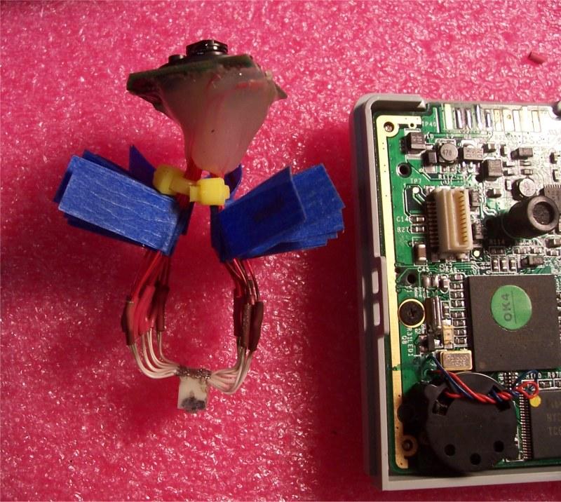
have too. It did take two attempts to get the imager to work. After removing the
daughterboard connector, I soldered wirewrap wire directly to the pads, labeled the wires,
and then coated the entire board with hot melt glue (my alternative to potting compound).
This took any strain off the very small solder connections at the pads. The next step was connecting these lines to the desoldered connector. I soldered 22 wires onto the connector and then joined both sets of lines in the middle. The first extension I made was about 6 inches long. The camcoder did not work with this extension. After reading of several other people's attempts at this same thing, with only one or two people who were able to successfully make the extension work, I gave up and set the camcorder aside, figuring I would have to buy and cannabilize a new camcorder for its imager daughterboard. I decided to try one more time before I bought a new one. I cut the extensions (leaving the daughterboard connections and hot melt glue blob alone) and started again with the connector. I soldered on 22 new wires to the connector and made the total extension only about 2 inches long. After rejoining all 22 wires, I was surprised to find that it worked as good as new. After taking this picture, I added hot melt glue to the wires on the connector to remove any strain on that side. |
||
|
Be very careful making these solder connections. They are tiny and
if you bridge any, you might not know it until the camcorder is permantly disabled by a
short to Vcc or common. A much better route would be to buy new connectors and make your
own extension without ever desoldering anything from either board. The connectors
are similar to these, but none are quite the same: If you find the right connectors, please post your findings to the Camcorder Hacks webpage at http://camerahacks.10.forumer.com/ This person was able to make the extension by getting connectors from a dead camcorder, which is another way to do this: http://camerahacks.10.forumer.com/viewtopic.php?t=1664
|
||
|
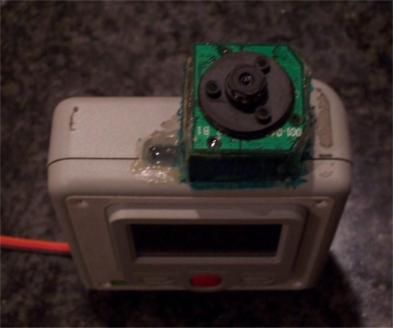
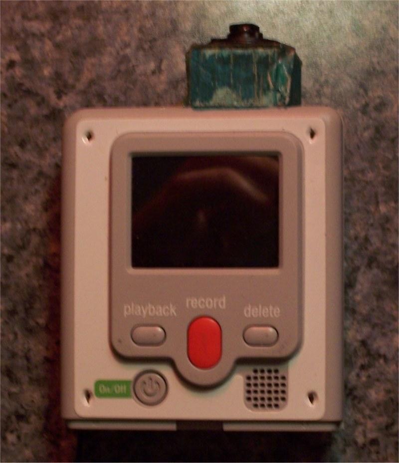
I could have left the whole setup out of the case to reduce weight, but
decided to to put everything back into the case to add a little protection. I
placed the imager with its extension facing forward along the long axis of the case, and
put a USB connector at the back end, where the batteries would normally be. With
this setup, the camcorder can be velcroed to the top of a wing, with the imager facing
forward and the LCD facing up. It can easily be viewed while installed and it has
minimal affect on drag. Power comes from the RC receiver. Below are two of the
installations I have made: attached to a Zagi EPP wing and also to a Stryker EPP delta
wing. Both are pusher configurations, and I have added foam to the CVS cam to tilt
the camera downward a little bit.
An extension can be made to work, so get out that tiny soldering iron tip. |