Dakota (Ritz) Single Use Camera Hack
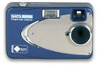
Ritz One Time Use Dakota: After the software and hardware hack on this camera, it becomes a regular, many-use 1.3 megapixel digital camera that can hold over 100 images between downloads. Before the hack, this camera costs $11 and is limited to 25 pictures. Ritz Camera then expects you to bring it back and pay $11 more to get your pictures "developed" and placed on a CD. You don't have to take this back to Ritz to get your photos. Download them all yourself using your own PC.
The first part of the hack is a firmware hack which does several things, including removing the arbitrary 25 picture limit. With that limit gone, you can fit as many pics as possible into the 16MB fixed memory. The total number depends on how complex the pictures are, but is usually between 55 and 70 pics. The firmware hack also changes the lcd display to total pictures taken, instead of the default pics left out of 25, and fixes a bug that incorrectly labels filenames for the pictures. In addition to the firmware hack developed by one dedicated engineer, there is a software package written by another engineer which takes care of downloading the pictures across a standard USB cable in JPEG format.
Because the camera uses a non-standard USB connector, you will have to make a USB adaptor connector or solder in your own standard USB connector into the camera, but that is a small price to pay for a 1.3 megapixel $11 camera. You are going to have the camera apart anyway to solder in the electronic shutter switch, right? As soon as I solder in the electronic switch, I will include pictures on its installation. This series of pictures shows the installation of a USB connector into a Dakota camera, allowing a standard USB cable to be used.
|
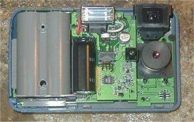
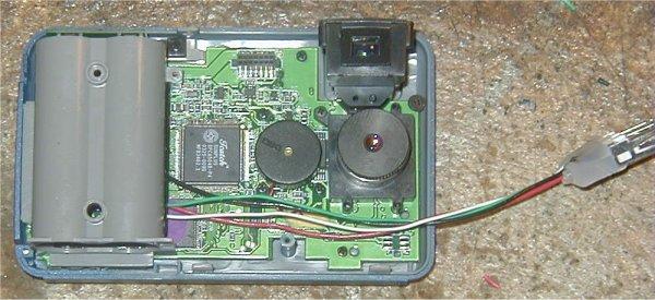
Here is the Dakota with the top removed. To get to this point, remove the sticker covering the 10 pin connector at one end, and then remove the three screws on the outside of the case and pry the top off. |
|
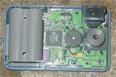
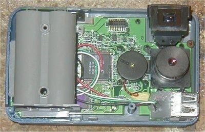
I have now removed the flash daughterboard. To get to this point, remove the two screws holding the daughterboard to the main board and pull up the flash daughterboard. Be careful with the big capacitor - it holds 330 volts at a few microfarad, which would be enough to zap you good if you grab the wrong wires on the daughterboard. |
|
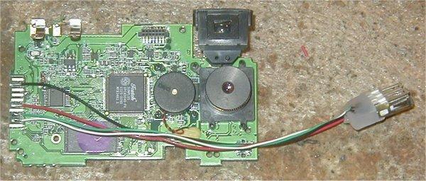
I have now removed the battery holder and soldered in a standard USB-A connector to the 10 pin conector on the left side of the main board. To remove the battery holder, you must first remove the main board from the case, then remove two screws from the end of the battery case, desolder a green (ground) wire from the end of the battery case, and remove two screws from the bottom of the main board holding the battery case. The 10 pin connector is blown up in the next photo. |
|
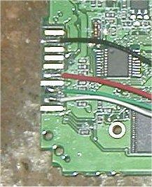
The USB black wire (ground) goes to contact 2, 7, or 10. I choose #2.
The USB red wire (+5 volts) goes to contact 6. The USB green wire (data +) goes to contact 8. The USB white wire (data -) goes to contact 9. |
|
I have re-installed the battery holder and have placed the main board back into the plastic camera case. |
|
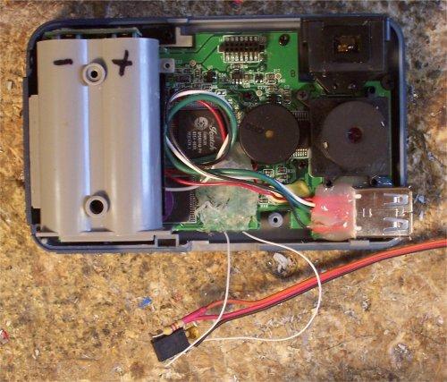
This shows the USB connector hot-melt glued to the main board. Make sure not to let any glue get into the USB connector itself. Next re-install the flash daughterboard. The after making a small cutout in the top casing for the opening to the USB connector, the casing can be snapped back on and the final three screws on the outside can be put back in to hold the whole thing together. You are done. |
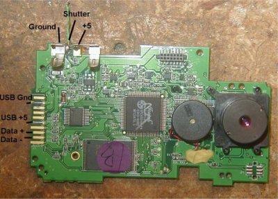 |
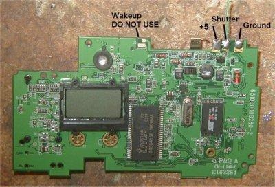
This shows the front of the main board with all unneeded components removed and the pinouts to be used with MR.RC-Cam's CamMan kit for aerial photography. The ground and +5 pins on the top are where the batteries (2 x AA) are normally plugged in. The camera has a voltage regulator which can use +5, so power from your receiver will work fine. The Shutter pin usually runs to the physical switch which is pulled to ground when it is depressed. The USB wiring on the left is used for the USB connection, as detailed above. |
 |
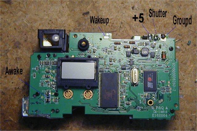
Here is the back of the main board. The WAKEUP function on this camera is tied to +5 (Vref), not ground as in Aiptek cameras. That is why I have it labeled DO NOT USE. The wakeup function on the CamMan chip pulls the pin to ground, not Vref. This could be a problem, however the camera goes to sleep only after 2 minutes of inactivity, so just take a picture no more than every two minutes. If you use the main board by itself with no other components, you will need to solder a momentary-on micro-switch between the WAKEUP pins to turn the camera on. |
 |
After hacking the Argus 3.1 megapixel digital camera, I decided to create an inverter circuit for the WAKEUP function on that camera. The Dakota has similar wiring requirements. You don't have to connect the WAKEUP function to the Dakota becuase it takes 2 minutes of inactivity to turn off, but shown here are all the wiring connections if you need to make that circuit. The WAKEUP pinout is the lower connection of the on/off switch. Be careful when soldering to this; you need to leave the sliding switch that normally turns the camera on uneffected by your new wiring. The AWAKE pinout is the right side of the indicated capacitor. |
 |
My final and favorite setup is to use the timeout version of my PIC switch. This switch ignores the AWAKE and WAKEUP routines, and automatically takes pictures every 1:30 keep the camera from going to sleep. Full details of this switch are on my PIC Development page. After testing, I coat the PIC and leads with hot-melt glue to avoid shorts and as a strain relief. |