I have built two solar powered planes as test-beds for the final version. Details
on the test beds are below. The final version is being built to set two world records;
longest straight line distance traveled and greatest altitude gain by a solar powered RC
airplane. The current distance record is 29.96 miles, and the altitude record is
6850 feet.
The FAI (Federation Aeronautique Internationale) maintains the world records, and the
relavent records are available at the FAI website. The current
distance world record is 48.21 km, or 29.9 miles. Both the distance and altitude world
records are held by Wolfgang Schaeper of Germany. The previous distance world record in
this category was 24.7 miles, held by Dave Beck of the US, and a web page describing his flight is online.

|
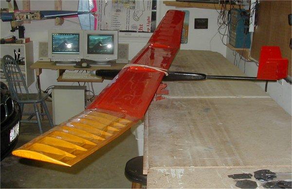
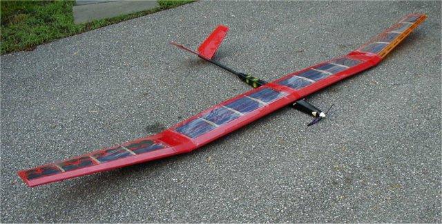
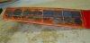
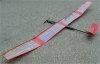
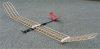
Entire plane with no solar cells. The top picture shows the entire
airframe. It is a lightweight fuselage with boom tail and a V-tail empenage.
It is a single piece 12 foot wingspan, high lift wing. |

|
Another view of the entire plane. This initial motor and prop setup, a stock can
05 directly driving an 8x4.5 folding prop, kept the current draw low, but made the climb
rate slow as well. It took approximately 10 minutes to reach several hundred feet in
altitude, but the plane was very stable the whole time and descended very slowly
also. |

|
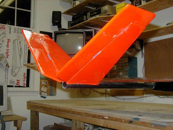
V-tail empanage. There is no external linkage. The first hand launch indicated
the CG was too far back, so I added a few ounces of lead weight to the nose and hand
launched it again. |
|
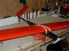
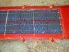
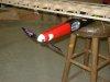
Temporary solar cells laid out in center solar cell bays. I have these
temporary solar cells for test flights, but hope to acquire better cells for the record
flight. |
|
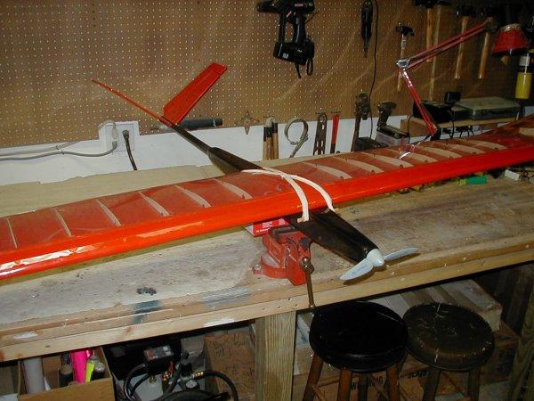
Center section before the clear covering was added to solar cell bays. Later
flights were made with a Graupner Speed 600, 2.5:1 gearbox, and 12x8 folding prop.
This combination worked great for climb and the plane continued to glide very well
also. I came across one end of the runway just a few feet off the ground and the
plane glided all the way to the opposite end; over 500 feet. That was with two 1500
mah 6-cell nicad batteries in parallel on board. Post flight engine test showed that one
battery was mostly discharged, while the other still had plenty of charge left for more
flying. My estimate is 1500 mah at 7.2 volts used, or 10.8 watt-hours total.
The flight lasted over 10 minutes, but assuming a 10 minute flight, we get 64.8 watts,
which is well within my solar panel budget. |

|
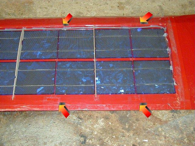
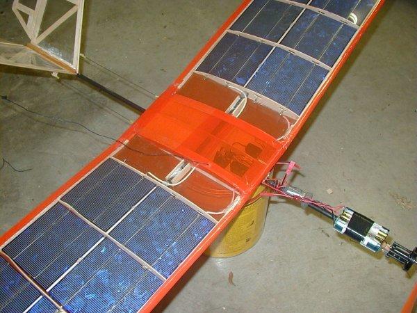
Center section with clear covering over solar cell bays. I used the clear
covering from a home supply store intended for insulating over windows in the winter.
The thin, double sides sticky tape bonds to Monokote very well and goes around
corners easily. To cover your own wing, put all four sides of the tape down first
with the top half of the tape still covered over by its white attachment. Lay out a
big piece of clear covering with extra hanging over the side. |
|
Remove the attachment to the top piece of tape and lay out the clear covering across
that one piece of tape, push down across the entire length of tape to get a good seal.
Remove the attachments from the other three pieces of tape and pull out the clear
covering taught over the rest of the wing. Push down to bond to the rest of the tape
and use a fresh X-acto knife to cut away around the edges. Use a heat gun or hair
dryer to shrink it down. |

|
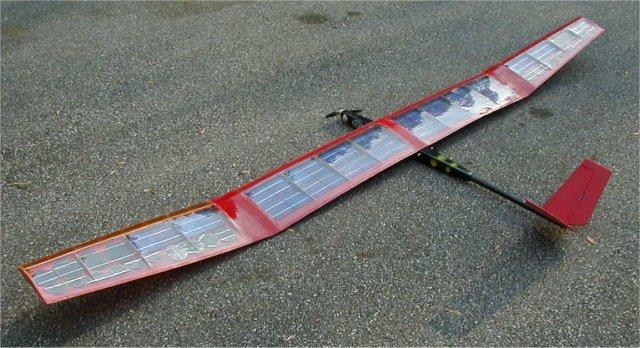
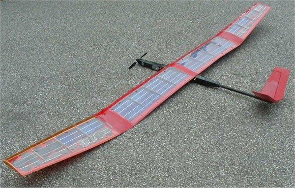
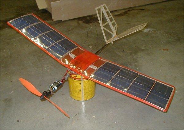
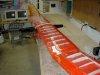
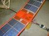
Four meter span, 48 watts of solar cells. The wing structure was built far too light
and it did not sufficiently support the solar cells. Graupner Speed 600, 2.5:1
gearbox, 12x8 folding prop, 25 amp ESC, three channels [ elerudders(2), throttle - esc] FLOWN
Wing #1, as pictured here and above, was designed for generic
solar cells. At the time I built the wing, I did not know exactly what size or kind
of solar cells I would be putting in it, and it was built mainly as a test bed. I
now have those solar cells: they are 100mm x 100mm, 2 amps @ .5 volts (1 watt) each in
direct sunlight. While the open bays I built into the center sections hold the
cells nicely, the wing tips don't efficiently hold enough cells for flight. . There are
two main parallel cell arrays, 20 cells each. 16 cells are in the center wing
sections, left and right. The other 4 cells are in each wing wing-tip to finish out
each 20 cell array. Solar cell electronics dictates that all cells get the same
amount of sunlight or you must use bypass diodes, but I decided the 4 cells in each wing
tip received almost the same amount of sunlight, so I skipped the bypass diodes within the
arrays. However, between the parallel arrays there are diodes for reverse voltage
protection coming out of each array on the positive leg. The negative legs are
common and the outputs of the diodes are tied together. Static testing with the
wings covered in transparent mylar gives 10.9 volts no-load and 4.40 amps short cicuit,
for a total of 47.96 watts. |
 |
There is a third, lower capacity array made up some smaller cells I bought from
another source. The third array is installed in both wingtips and wired in series.
The total of almost 48 watts will be enough to charge the batteries during
power-off flight, but a battery must be used with this wing during testing for climbing to
altitude. I have moved to a 8 cell 1500 mah NiCd pack for flight testing, which is
installed in parallel to the solar cells. |
 |
The solar cells get warm very quickly and the energy output drops as the temperature
goes up. In just a few minutes, the completely sealed solar arrays frosted
part of the covering with condensation from the heat buildup inside. I added
ventilation holes to the front and back of every cell section between ribs. This
ventilation will allow that heat and trapped moisture to escape while in flight. |
|
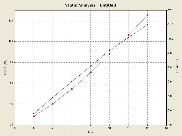
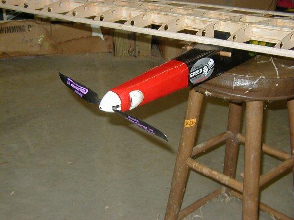
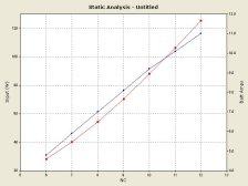
A smaller power combination was chosen for low cost, light weight, and low current
draw. Analysis was done on many motor / gearbox / prop combinations available on
eBay over several weeks, using Motocalc. I bought a Speed 400 motor, 4:1 planetary gearbox, and 11x8 folding
prop on eBay. This combinations showed the best
results, even over most of the low cost brushless setups that were also
available. The final numbers from Motocalc were close to experimental data on the
motor setup after I received it. Motocalc estimated 75 to 80 watts as the best point
on the curves for voltage and current inputs, and gave a top efficiency at 9.5 to 10 volts
and 8 amps. Using an 8 cell Nicd pack running at 10.5 volts peak, the motor setup draws
8.4 amps. This is right in line with the plots from Motocalc. |
 |
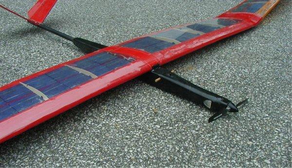
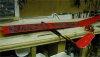
I have added lightening holes to the fuselage. The total weight of this fuselage
is now considerably less than the weight of the fuselage on my Astro Challenger, a much
smaller plane (on the right). |
 |
I have also extended the nose to help balance the plane. Getting the CG correct
required more lead in the nose than I wanted to add. The motor moved forward 6
inches gave the same result. The center of pressure has been moved forward by this
additional area in front of the wing, but I had plenty of static margin left. |
|
A very short test flight with the Speed 400 motor showed that it does not have enough
power for climbing. I replaced the Speed 600 and 2.5:1 gearbox back onto the plane.
This combination has successfully test flown and the plane was able to climb.
I originally built the wing very light and flexible to allow for the load of cells.
The test flight with this configuration showed that the wing tips are too flexible
and oscillated wildly. This had never happened when the wings were empty - the extra
weight of the cells must be enough to induce the vibration. Fortunately, wing #2 is
much more stiff. |
 |
Wing #2 has been designed and is under construction. It is being built
specifically for the 100mm x 100mm cells; the ribs, front and back spars, and leading and
trailing edges create openings 105mm square. The solar cells fit percectly in the
openings, so there is no need to have open bays to hold the cells. The solar cells
will be held in individually and soldered together once each section is complete.
There is enough flexibility in the installation to allow the wing to bend without breaking
the cells, while still holding them sufficiently for flight. |
 |
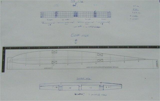
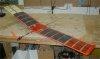
Here is the center section of the new wing. The center section is flat (no
dihedral), 20 cells wide and 3 cells deep. |
 |
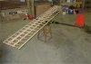
Here is the entire new wing. The plug-in wingtips are 6 cells wide and 3 cells
deep plus 2 more cells at the very ends, for a total of 20 cells each. That makes
100 cells and 100 watts total. |

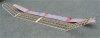 |
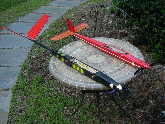
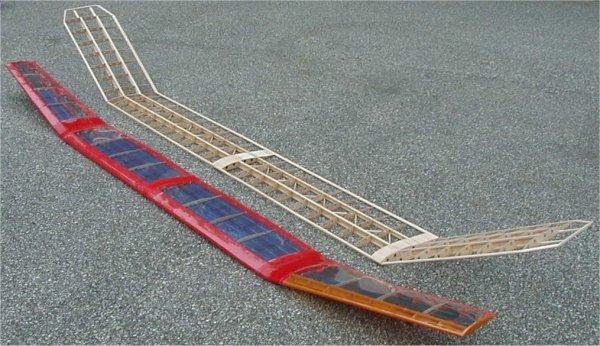
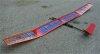
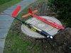
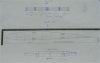
Here are wings #1 and #2 together. Wing #1 holds approximately 48 watts of solar
cells. Wing #2 holds 100 watts of solar cells. It has a slightly larger chord
and wingspan, but is much stronger. Wing #1 is also a single piece, so transporting
it can be a problem. Wing #2 comes apart into three pieces, so it stores and can be
moved much easier. The new wing has been flattened and now has no dihedral. The
canard of similar design is being built for a final configuration that will include 100
watts os solar cells in the main wing and 60 watts in the canard. |
| |
|
 |
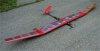
Mini Solar Powered Electric - I built this 34" wingspan, 9.25" chord
plane as a test bed for the solar cells used in the large glider above. The 16 solar
cells put out 8 volts at 2 amps in full sunlight. The small electric motor draws 1.5
amps at 8 volts at full power. GWS ICS-100, 11:1 gearbox, 13x9 prop, 2 amp ESC,
three channels [ elerudders(2), throttle - esc ] FLOWN
|
 |
Update on the mini: The first test flight showed the plane did not fly slowly
enough. I made a new lightweight smaller tail with thread pull-pull elerudders,
added wing extension to lighten the wing loading, and replaced the thick boom with a
smaller diameter carbon fiber boom. Total weight is now 19 oz. The plane
now has a 65" wingspan for a total of 4.17 square feet of wing, giving a wing loading
of 4.55 oz/sq ft. |