Telebee Heading Hold Piezo Gyro
I needed a piezo gyro to replace an ancient Futaba G-153BB mechanical gyro that I had been flying on a Shuttle ZXX for several years. The Futaba gyro still worked fine, but the battery draw was higher than a piezo gyro, so I wanted to upgrade. The Century piezo and Thunder Tiger piezo gyros on my other choppers worked great, so I decided it was time to move out of the dark ages.
I looked around for a simple piezo to buy, and there are many available. While looking through the stuff at the local hobby shop, the owner told me he would sell me his never-opened Telebee 701 for $50. He said "No one can get these things to work properly. Take it off my hands." I hesitated until I did a little reseach on the web. Many people have had two problems with these gyros; in setup, and failing after they were flown for a short time. It takes some extra care to ensure the setup is done correctly, and there are fixes for both the failure problem, plus some extra stuff that can be unlocked with a little work. I went back and bought the gyro for $50. These gyros can be had for anywhere under $100. Get your best deal and go to work.
Similarity to CSM ICG 360 Gyro:
The CSM ICG 360 gyro is very similar (practically identical functionality), and the setup
instructuctions that come with that gyro are very good. The CSM ICG 360 gyro can also be
programmed from a PC, and that software will work on the Telebee. You can download
the PC interface and instructions at this page http://www.rcmodels.org/csm/icg360_gyro.htm,
and I have them mirrored here: Airtronics RD6000 & ICG
360 gyro-setup PC interface software
PC interface instructions CSM ICG 360 Gyro instructions
A excellent pages is available detailing the setup of the Telebee at http://bellsouthpwp.net/f/r/fritzthecat/gyros.html This page also has schematics for the interface needed to use the CSM PC interface software. I have those schematics mirrored here: Cable-1 Cable-2
The side of the Telebee gyro has a 3-pin connector slot that is used to connect to a PC. Use a standard Futaba 3-pin servo connector and use the standard colors on the servo wire for the cable schematics listed above: white towards the top of the slot, red in the middle, black at the bottom. The other end of these three wires plugs into the parallel port on the back of your computer.
External links to other setup pages:
I have put together all the pieces on setting up the Telebee I could find scattered across
the Internet.
http://www.mfarchive.modelstuff.co.uk/mf007/planetalk.htm#telebee
http://members.tripod.com/heliplanes/Telebeecsm.htm
These are pretty much copies of each other. The original seems to have come from Rotory Modeler Magazine.
http://www.telebee.com.hk/press1.htm
http://www.crazyhobby.net/703.html
http://www.hhiheli.com/telebee_setup.htm
http://www.rchelibase.com/gyro/telebee.pdf
http://www.ronlund.com/telebee_setup.htm
Before Installation:
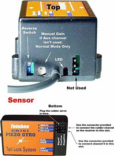
Before you even install this thing, take a look at how it is put together. There are
two main pieces, the "sensor unit" and the interface box. The sensor unit
is actually everything. The black cable that runs to the interface box goes directly
to the pinouts. The interface box contains a capacitor to smooth out voltage and a
resistor to protect from too high a voltage. They could both have been put into the
sensor unit easily. The rest of the interface box is a big ground plane; it adds
nothing. I guess Telebee wanted to make their gyro seem more substantive. I
have not done it, but the interface box could easily be removed and the black wire brought
directly to connectors. This would be nice for very small choppers. Remember
to put in a capacitor to smooth the voltage input. The resistor is up to you.
Many problems reported for failure of this gyro involve the sensor box breaking and the circuit boards inside breaking, either due to the case breaking, or simple vibrating apart internally. Open the bottom of the sensor box and look inside. There are three circuit boards; one of them has the sensor unit mounted vertically. The sensor unit is a Tokin CG-16 piezo rate sensor. This sensor is excited by rotation about it's long axis. This is important to note for the orientation of the sensor box during installation. Carefully (!) stuff foam into the center section between the three circuit boards. Put very thin foam around the outside of the boards between them and the case. Be careful not to bend any of the board conections or break anything off. With this internal suppport, the gyro should be safe from the internal pieces breaking apart. The next step is to reinforce the case itself. With the sensor box reassembled, wrap some duck tape or strapping tape around the case, leaving the holes in the case near the interface cable accessible. You will need to be able to get to those holes later on during setup and programming. Don't overdo the tape - you just need enough to give a bit more "wall" strength to the case.
Installing:
The directions say to use the arrows on the case for orientation during sensor
placement. Ignore that - remember that the the piezo sensor is mounted
vertically in the sensor box and it senses rotation about it's long axis. Therefore,
in a chopper, the bottom of the unit should be mounted down. That places the sensor
unit vertically and it will sense rotation about the chopper's vertical (yaw) axis.
If you are placing this gyro in a plane or chopper to damp out pitch, the bottom would be pointed out the left or right wing and the top would be pointed out the other wing. To damp out roll, the bottom is pointed towards the nose or tail, and the top would be pointed to the other end of the vehicle. This 180 degree orientation does not matter because the unit has a reverse switch. If it give servo commands opposite what you need, you will reverse the gyro. Some gyros do not have a reverse switch, and instead require you to turn the gyro over 180 degrees. The CSM ICG 180 is one example of this type of gyro.
The easiest way to check to what axis the gyro senses is to plug it into a receiver, plug a servo into the gyro, turn on your transmitter, and twist the gyro sensor box. With the gain control cable not connected, the gyro will default to mode 0 operation, or standard non-heading hold mode. When you are happy that you understand which axis is being sensed, you are ready to install it on the air vehicle.
When you install the gyro, use the supplied double-sticky tape on a clean surface. Use acetone or alcohol to get a CLEAN surface, and let the cleaner evaporate before you install the gyro. Peel back one side of the tape and place it on the bottom of the sensor case. Do not remove the other side of the sticky tape yet. Trial fit the sensor box in place, making sure you can get to the holes in the case next to the interface cable. Again, you will need to be able to get to those holes later on during setup and programming. Make sure the interface cable reaches to where you will be placing the interface box (usually next to the receiver.) Now remove the other side of the sticky tape cover and put the sensor box in place.
Setup:
Before you plug in the rudder servo to the interface box, plug it directly into receiver.
Command a right yaw (nose to the right) with the transmitter and look at how the
servo moves. Remember that - next we will create a left yaw on the gyro, and it
should command a right yaw output to the servo, the same as if you had commanded a right
yaw. Now plug in the rudder servo to the interface box and plug the interface box
into the rudder channel on your receiver. Don't worry about the gain control wire
yet. With the chopper stationary, command a right yaw with your transmitter
joystick. The servo should move the same direction as before. Now pick up the
chopper by the main mast so that you can yaw it left and right easily. Watching the servo
arm carefully, move the nose of the chopper to the left quickly. It doesn't have to
be very far, but the faster the acceleration, the easier it is to see the results.
The gyro should counter that left yaw with a right yaw command to the servo. You
have introduced a yaw to the gyro, which it countered with a command to the opposite
direction. If it does not go the correct direction, flip the reverse switch on the
side of the sensor box. You did install it so you could get at that switch, didn't
you?
At this point, you should have the gyro physically installed on your chopper and moving the rudder servo in the correct direction to counter uncommanded yaw. We now need to setup up the gains for standard or normal mode. Don't worry, we will get to heading hold, but normal mode comes first. If you don't have an extra channel on your receiver to command the normal (and heading hold) gain, you will have to adjust it with the manual gain input on the side of the sensor box. You will also not be able to use the heading hold feature.
Stick gain: (VERY WRONG)
The Telebee gyro has a built in default stick gain of 2 over most of the gyro gain curve
(for both normal and heading hold). If you are very close to no gyro gain (< 25%), the
stick gain is also very small. Stick gain seems to be equal to gyro gain from 0 -
25%. Gyro gain from 25% to 100% makes stick gain equal 200%. That means that
over the upper 75% gyro gain area, when you command 50% left stick, the servo will move
100% to the left, and vice-versa to the right. The result of this is that with the
ATV of your rudder channel set to 100% both directions, only the first half of your stick
inputs have any effect. The far left and far right stick commands past 50% throw
each way do nothing. That is not the way most gyros work. The stick commands should
be passed directly to the servo with a stick gain of 1, and the gyro sensor input is mixed
in to the final output, with the gyro gain set by the user. I have seen this
using two radios at home, both JR 8103s, one transmitting PPM and the other PCM. I
have also read abotu this in newsgroups discussing the Telebee gyro. To verfiy this
on your gyro, slowly move the rudder stick to the left. The servo should move in
conjunction with the stick until you reach half throw to the left. At that point,
the servo should stop moving. You have actually reached full travel from the servo,
just twice as fast as normal; the rest of the stick movement will have no effect on the
servo . The fastest way to make your entire stick movement go directly to the servo
is to set rudder ATV to 50% on both sides. With ATV set to 50%, slowly move the
stick to the left again. The servo should move all the way to full stick throw in
both directions. At full stick throw with 50% ATV, you are actually commanding the
servo the move 50% in that direction. The gyro has multiplied your input by 2
(stick gain = 2) and commanded the servo to move 100%. Here are some discussions on
this stick gain problem.
http://www.raptortechnique.com/telebee-eclipse7.htm
http://www.heliguy.com/nexus/bbs/messages/2646.html
http://www.centuryheli.com/support/manuals/CN2238telebee.pdf
Nerd section:
If you have a radio that allows you to see what the exact servo outputs are, this is much
easier to see. My JR 8103's have display that show exactly what each channel is
receiving in the way of pulse-widths. The center position of any servo is set to 1.5
ms. 100% throw in one direction is 1 ms and it is 2 ms in the other direction.
This is an industry standard for all servos. The $1000 servos we use on the
Shadow 200 Tactical Unmanned Aerial Vehicle for the US Army use the exact same control
method.
The instructions listed on the above pages cover everthing else you need to know. I wanted to add my two cents to the effort here, with the stuff I thought was missing on other pages.