The 8 foot wingspan prototype flying wing was built over a wing jig that creates the
washout needed to make a true flying wing stable (without fly-by-wire computer
corrections). This jig is similar to the jig that the Klingberg Flying Wing is
constructed upon, but my prototype has different washouts, spans, sweeps (leading and
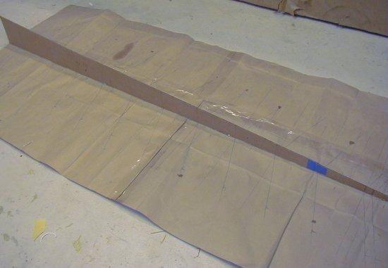
trailing edge) and airfoil. A side view of this jig can be seen in the picture
below. The wing is built in two halves, with the main spar running down the
corrugated cardboard jig, and the wing ribs sitting on the spar and running down to the
trailing edge sheeting. The right half of the wing is built on the side closest to
the camera, and the left half on the side farthest away. The right center wing rib
is placed at the highest section of the jig (left end) and the ribs are placed at a
slightly decreasing angle as you approach the tip (right end). When the ribs are all
glued to the main bottom spar and lower trailing edge sheeting, the upper main spar and
upper trailing edge sheeting are added. The wing half is then removed from the jig
and the left half of the wing is built on the other side, this time moving from right to
left (center to tip). The wing halves are then joined and a main spar made of spruce or
carbon fiber is used to strenghten the center section. The twist (washout) produced
by the jig allows the wing tips to attack the wind at a lesser angle of incidence than the
center section. The reduced angle of attack at the tips keeps them from stalling
before the center section and creates an induced dihedral in the wing. If you are
going top build this wing, make sure you understand this twist and you build the wing
sections correctly. If they are reversed, your plane will not fly. The measurements
for the jig and rib placements are all below. I will be happy to answer any
questions. The wing lacks somewhat in longitudinal stability, but the shear beauty
of a pure flying wing more than makes up for any bad yaw tendencies. This is a
thumbnail, so click on it to see a larger version.
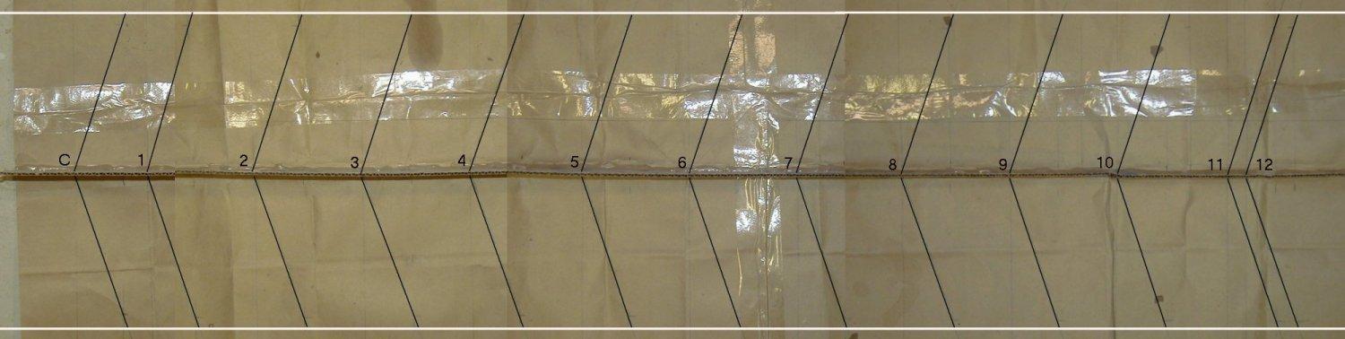
I took several pictures with my digital camera of the plans from directly above and
joined them into one image. The distances and rib placement are listed here. The
wing jig (elevated cardboard piece) is 4.25 inches high at the center rib and .75 inches
high at rib #12. It is a straight line between those two points. This image is
a thumbnail also, so click to see a bigger version.
| TOP SECTION: Left half of wing BOTTOM SECTION: Right half of wing Center rib (wing jig 4.25 inches high) -> rib #1 : 3 inches -> rib #2 : 7.5 inches -> rib #3 : 12 inches -> rib #4 : 16.5 inches -> rib #5 : 21 inches -> rib #6 : 25.5 inches -> rib #7 : 30 inches -> rib #8 : 34.5 inches -> rib #9 : 39 inches -> rib #10 : 43.5 inches -> rib #11 : 48 inches -> rib #12 : 48.75 inches (wing jig .75 inches high) |
 |
| The angle that each rib is attached to the main spar was calculated with the chord of each wing rib to give a leading edge sweep of 20 degrees and a trailing edge sweep of 8 degrees. These angles, combined with the calculated span gives a total surface area of 1200 square inches to the last wing rib. The rounded wing tips on the prototype add a few square inches to the total. To achieve the same sweeps I have in the wing, draw a line straight out from the jig 6 inches. Turn 90 degrees and go 2 inches. Draw a line from the jig to this point and you have the correct angle to place each wing rib on the main spar as each wing half is constructed. | 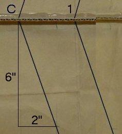 |