Power must be supplied for the microcontroller and other instruments that
reside in our remote control plane. It is therefore necessary to look at
how much power each piece of our system will draw in order to design an
effective power supply. The table below indicates the voltage that each
instrument needs as a supply voltage. This table also indicates the current
that each instrument will draw.
Power supply topology:
The power supply topology has undergone many levels of redesign. We had
ideas to use batteries with linear regulators, DC/DC boost converters,
and DC/DC buck converters. After careful consideration we have decided
to use a 12 volt lithium battery with a 5 volt step-down switching DC/DC
power converter. This will supply the plane with five volts. The 12 volts
lithium battery will also provide power for a 9 volt regulator. This regulator
will supply voltage for the modem. There is also a 9 volt battery on the
plane. This is used to supply voltage for the launch circuitry, and a step-up
DC/DC boost converter. This converter provides a regulated 12 volts for
the altitude and airspeed sensors. Instead of spending time and frustration
at the bench designing the DC/DC converters, we decided to use a package
by Power Trends Inc. They make a condensed switcher which suits our needs
perfectly. The Power Trends 5141 chip will step-up to 12 volts, while the
5101S will step-down to 5 volts. The two chips will be able to handle 230mA
@ 9 volts, 100mA @ 5 volts, and 20mA @ 12 volts. These chips will provide
the backbone for circuitry on the plane.
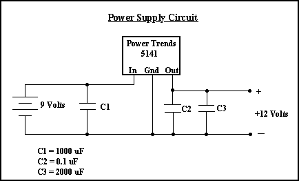
For this circuit a Power Trends chip was used. A set of capacitors are
used to stabilize the output. C2 was used to filter for radio frequency
interference, and C3 was used to smooth voltage spikes caused by current
draw changes. This circuit worked wothout any flaws.
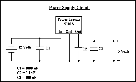
5 Volt Power Supply:
This supply was also built using a Power Trends chip. The output also had
a set of resistors to stabilize the voltage. C2 is used again for radio
inferference, and C3 is used to smooth voltage spikes. this power supply
also worked without any flaws.
9 Volt Power Supply:
This was accomplished using a LM7809 voltage regulator. The input for the
chip was the 12 volt battery. The only draw for this power supply was the
modem. It also worked great, without any flaws.
Design Considerations and Problems:
For this project it was important to keep weight to a minimum, and provide
regulated power for all of the components. To solve the weight problem
we used lithium batteries, which are very light. In order to provide regulated
power, we used regulating sources for each. The power trends chips were
a pleasure to work with. They were hassle free, the only tough design condition
to account for was the large current draw when the launcher was fired.
The current spike went to approximately three amps for a split second.
To account for this a large capacitance was used to smooth the voltage.
So the current could be drawn and the capacitance would hold the voltage
supply high enough for the bourds to not turn off.