ENGINE TACHOMETER APPLICATION PAGE
|
Objective:
The engine tachometer is a critical measurement on an aircraft. The pilot
needs to know how his engine is performing at all times. We felt that this
was an important measurement to include in our project. To implement this
sensor we used an Omron IR sensor, and a Schmitt trigger. The output was
then TTL compatible, providing either 0 or 5 volts for the microcontroller
to read.
Implementation:
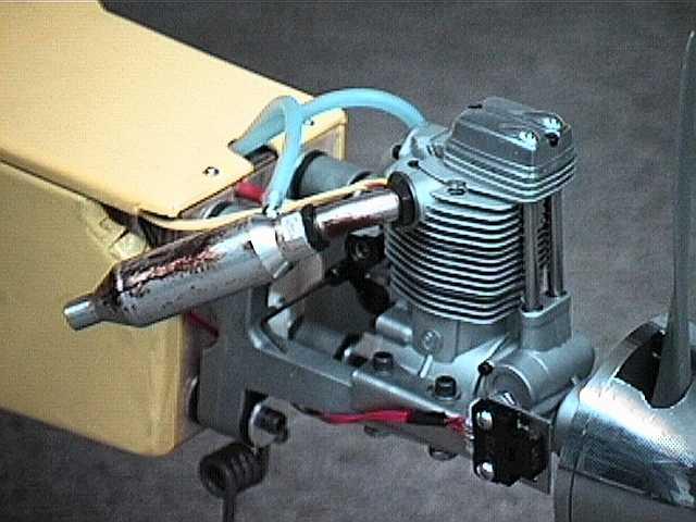
As mentioned earlier, we used an IR sensor to measure the rpm of the engine.
The IR sensor sends out a signal which is either absorbed or reflected
off of the back of the spinner. When the signal is reflected, the sensor
is considered active. The back of the spinner is half metallic silver and
half flat black paint. The black paint is used to absorb the IR signal.
The circuit used for the tachometer can be seen below. The resistors R1
and Rf were chosen as follows: When the sensor is "active" the transistor
between nodes "out" and "L" is on. This then lets current flow through
R1 pulling the voltage at "out" low. R1 was chosen to be big because we
wanted a small amount of current to flow. In this case, 250uA will be drawn
when the transistor is on. When the transistor is off then the voltage
at node "out" is five. The resistor Rf is a trimpot with a value of 1K
ohms. This resistor limits the current through the diode, or emitter. Rf
can be found by using the equation:
Rf > (Vcc-1.5)/Imax
In this case, Rf was set to give maximum intensity giving the maximum
range for the sensor. Rf was then trimmed so that the output could be read
with the sensor at any distance up to 1 inch from the sensor. With Vcc
= 5V, and Imax = 30mA, then Rf = 117 ohms.
Picture of the tachometer sensor on the engine mount:
Circuit Schematic:
Design Considerations and Problems:
When designing the sensor, the working range of the sensor was a major
consideration. It needed to be great enough so that the sensor did not
need to be mounted right next to the spinner. Secondly the current draw
needed to be considered. This is why a trimpot was chosen. At full rpm
the trimpot could be set to just make the IR sensor "read" the spinner,
and consequently setting the current at a minimum. No problems were enountered
with this circuit design or the sensor application.
A.F.T.S.
Home
Page
|
Sensors
Application
Page
|
Bill Glenn
Pat Malloy
Greg Norton
AFTS Project Group
|