One channel of the radio-control system is used by the human pilot to either allow the
computer to fly the aircraft, or to take control of the aircraft himself. The channel used
has a toggle switch on the receiver, providing only two positions. The PWM receiver output
is averaged by a RC filter, giving a DC voltage reading of about 0.15 V in one position
and 0.27 V in the other. A comparator circuit compares this voltage to a standard of about
0.2 V, and outputs a logic 0 or 1. The output of the comparator is then used as the select
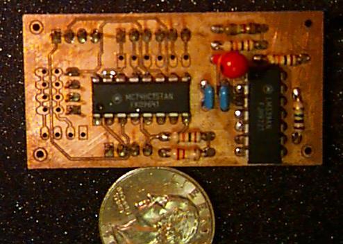
signal for a quad 2:1 multiplexor. This system is independent of the computers and other
electronics, allowing the human pilot to take control of the airplane at any time. The
completed board measures about three inches by one inch.
During the data-collection phase, this board is not needed, and is replaced by a circuit
which splits the receiver signals into two paths - one to the servos and one to the HC11.
This circuit is combined on the same board as the serial transceiver.
Schematic (pdf)
PCB layout (pdf)
Back to Avigator
Revised 6/2/99