Aircraft Flight Telemetry System (AFTS)
Bill Glenn, Pat Malloy, and Greg Norton, a group of EE seniors at Bucknell, built a remote control plane with tachometers, airspeed, altitude sensors for telemetry. Their home page was called AFTS, aircraft flight telemetry system. I downloaded a complete description of these circuits from their home page. It was an excellent page with lots of good information. Unfortunately, that project was completed several years ago and the page is no longer available at is former location, http://www.eg.bucknell.edu/~malloy/. Pat Malloy was gracious enough to let me mirror their information here. These are the four main pages:
Analog to Digital Converter
The sensors made for AFTS were designed to be fed into a single chip CPU, and from there into a radio modem. This chip has analog to digital converters (ADC's) built in. While my newer processors (BasicX-24 and ISOPOD) have ADCs, my older processors did not. I have found specifications for several ADC's on the Internet. There are several ADC's at http://www.doc.ic.ac.uk/~ih/doc/adc_dac/. Here are some ADC's with different capabilities that I found on the Internet.
1) 10 bit, 11 channel ADC : http://www.doc.ic.ac.uk/~ih/doc/adc_dac/adc11/
<mirror>
Based on the Motorola MC145050P or the Texas
Instruments TLC1543.
2) 8 bit, 4 channel ADC : http://www.doc.ic.ac.uk/~ih/doc/adc_dac/deck/4chan8bitadc.asc
<mirror>
Based on the ADC0833CCN, available from Digikey.
3) 12 bit, 8 channel ADC : http://archives.e-insite.net/archives/ednmag/reg/1997/102397/22di_05.htm
4) 8 bit, 8 channel ADC : http://www.phanderson.com/printer/0838/0838.html
Based on the National Semiconductor ADC0838.
You might want to try using any of the ADC's from Analog Devices.
Some examples are the AD7811 / AD7812, AD7822 / AD7825 / AD7829, AD7714 or
AD7856. These can be set up closely to the specs shown in #2
above, but the pinouts and control signals on these ADC's are slightly different.
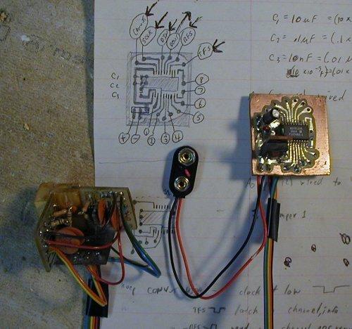
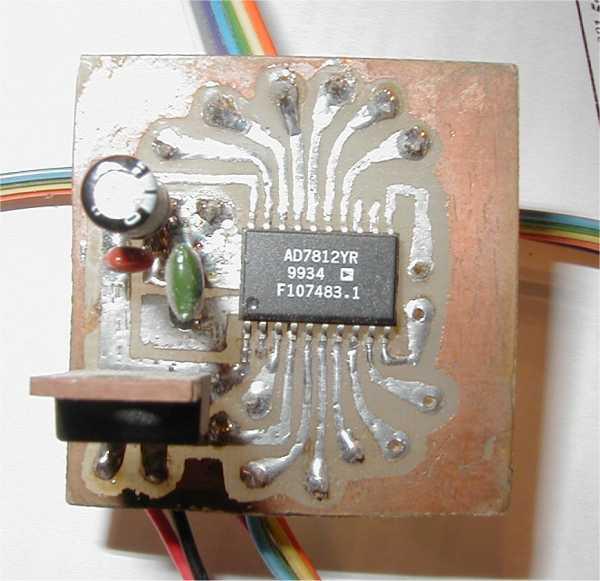
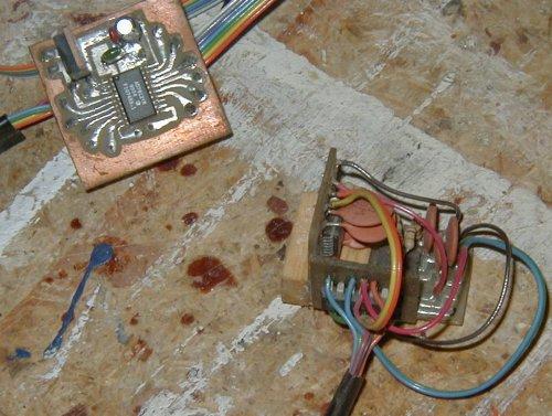
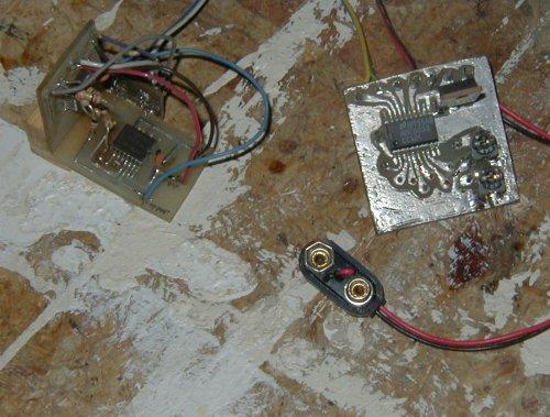
Here are the ADC boards I have put together.
|
AD7812 - I made this board with capacitors to smooth out the supply voltage (also the reference voltage), and a 7805 voltage regulator as the power supply. |
|
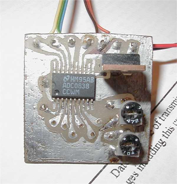
ADC0838 - Here are some views of the ADC with the Analog accelerometers, and a close-up of the board I built to hold the ADC0838. I added two micro potentiometers to channels 1 and 2 for testing. This board also has a 7805 voltage regulator as the power supply. |
AVIGATOR
The MUX will be built according to specs found on the Internet. Stephen Stancliff, a student at the University of Florida, built a plane controlled by a small on-board computer running a nueral network. It is called human skill modeling. His home page is called Avigator and the URL is http://mil.ufl.edu/avigator/. I also have a mirror of those pages here. He also pointed me to Analog Devices as the source for my attitude sensing; he suggested which of Analog's accelerometers to use and how to employ them. I am indebted to Stephen for his help.
RC Receiver to Computer Interface (via ADC->parallel port / PIC->joystick port)
The fly-by-wire capability requires that the computer on board the aircraft be able to read the outputs of the RC receiver. The computer then analyzes these servo commands and sends the appropriate signals to the servos via the serial servo controller.
These PWM RC receiver signals are passed through an RC (that's R-resistor C-capacitor; not RC-remote control) circuit and the resulting analog signal is read by the ADC mentioned above. Here is an explanation of how to convert PWM signals to analog.
My original design for this fly-by-wire capability was to convert the PWM signals from the RC receiver to digital form and read them via the joystick port. Cord's R/C Model Electronics web pages at http://home.t-online.de/home/C_Jhm/ has the perfect device for this. I have this RC receiver to joystick interface mirrored here.
RC Transmitter to Serial Servo Controller Interface - by Mike Berg
The interface is designed to convert the multi-channel output of a R/C transmitter into RS-232 serial data formatted to operate a Scott Edwards SSC II multiple servo controller. Mike Berg asked me to include these files here to allow anyone to access them. They are also contained on Yahoo UAV E-Groups page, under Files/RC_serial.