|
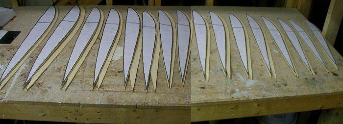
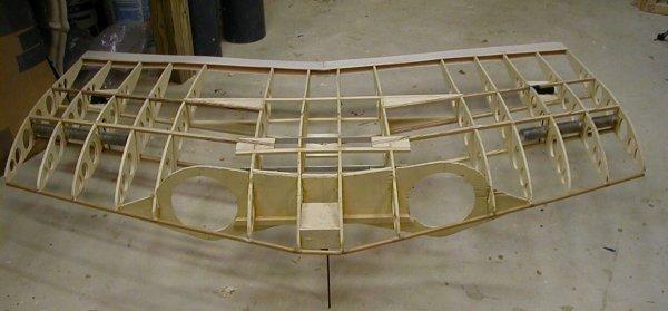
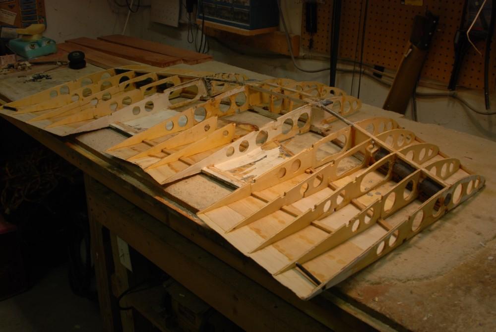
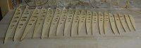
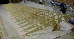
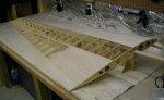
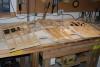
The wing ribs have been cut from 3/16" lite-ply. This is the initial layout
of ribs. |
|
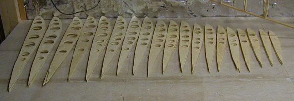
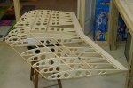
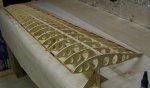
The lightening holes have now been drilled out from the wing ribs. |
|
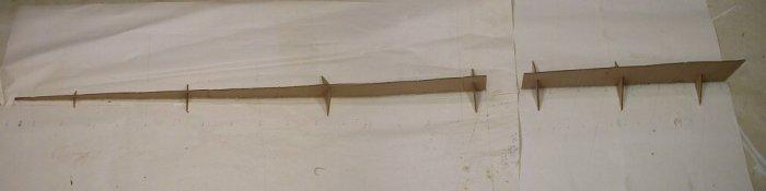
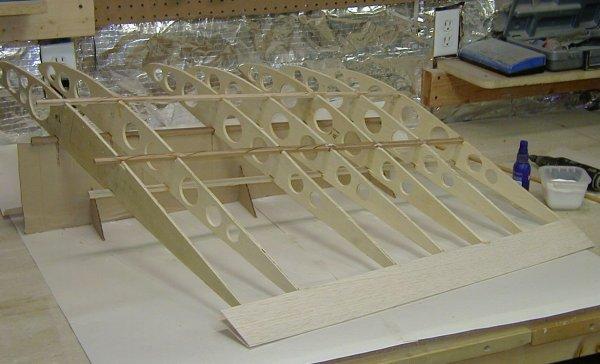
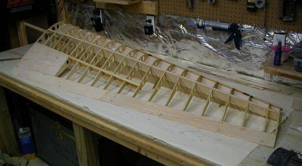
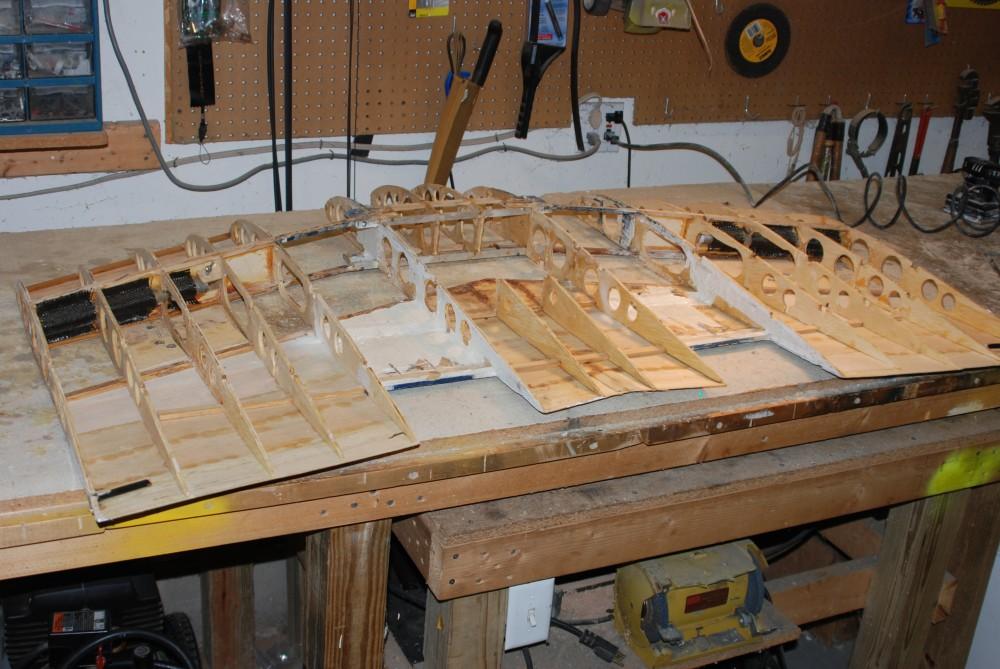
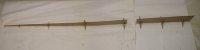
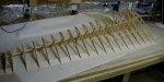
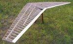
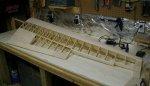
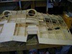
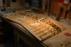
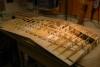
This is an overhead view of the two wing jigs. The jig on the left is the wing
tips jig, and the jig on the right is for the center section. The left half of the
wing is built on this side, and the right half is built on the opposite side. For a more
detailed explanation of how this type of wing jig is used to build washout into the wing,
please take a look at the prototype construction
page. |
|
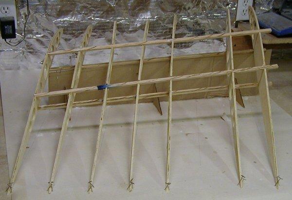
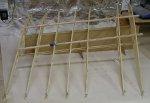
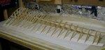
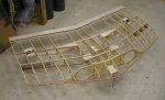
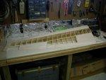
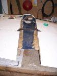
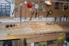
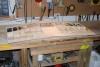
This is the left center wing section sitting on the center wing jig. |
|
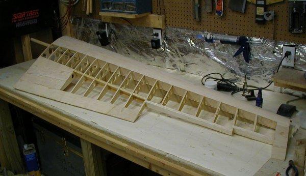
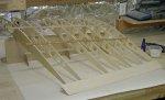
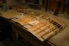
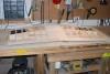
This is the right center wing section sitting on the center wing jig. |
|
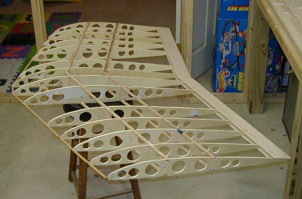
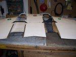
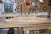
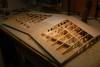
This is the two center sections joined together. |
|
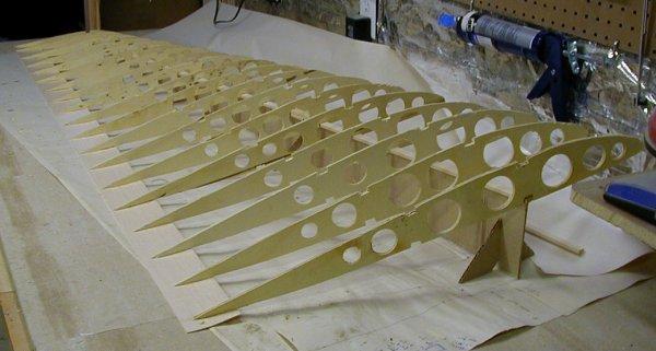
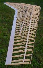
This is the left wing section on the wing tips jig. |
|
Another view of the left wing section. |
|
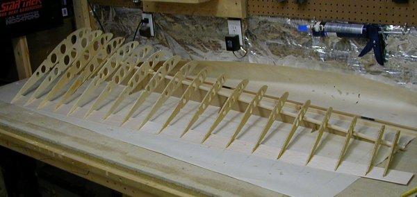
This is the right wing section on the wing tips jig. |
|
Another view of the right wing section. The jig and wing section have been
turned around on the workbench to add the leading edge arrowshaft. |
|
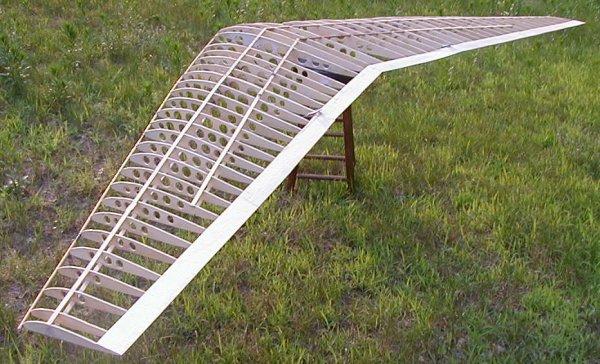
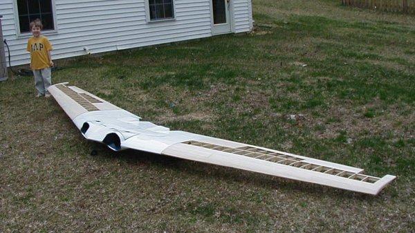
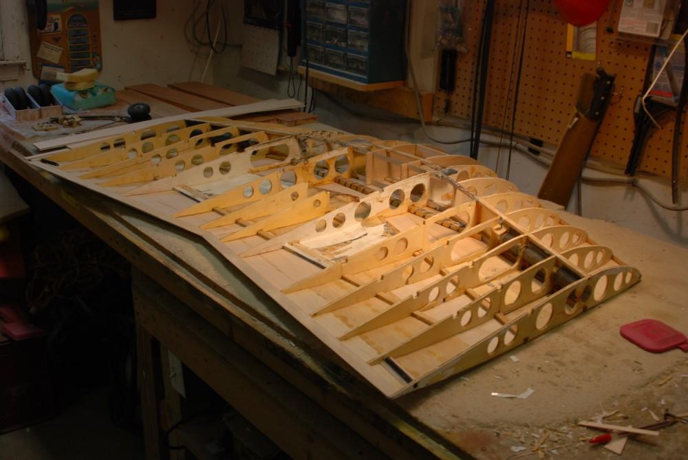
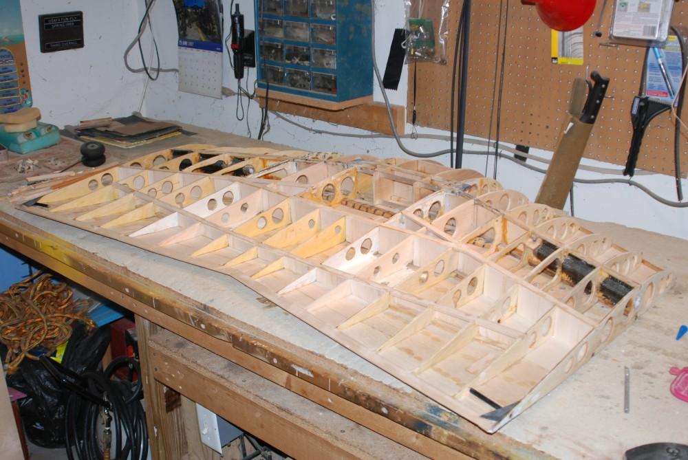
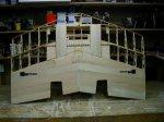
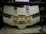
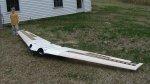
Here is the entire airframe. |
|
Another view of the entire airframe. |

|
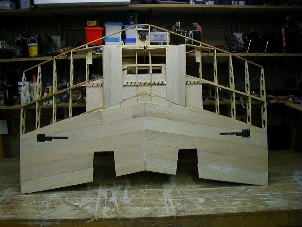
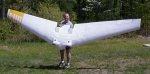
I have added the main wing joiner plug-in dowels (1 inch diameter) and the support
tubes. The wing is 16 feet across. I have lots more sheeting and reinforcement
to add before I start on the mechanics, engine mounts and ducting, electronics, and
retracts supports. |
|
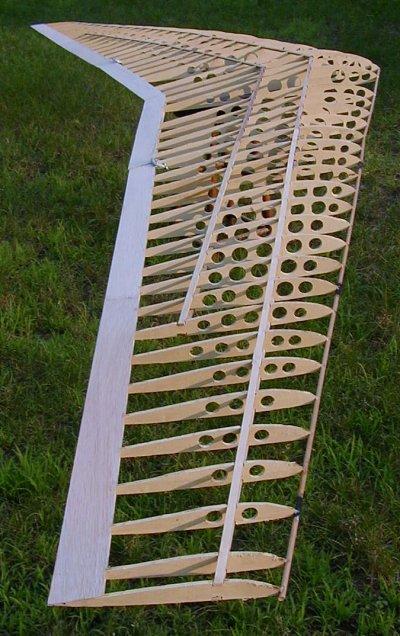
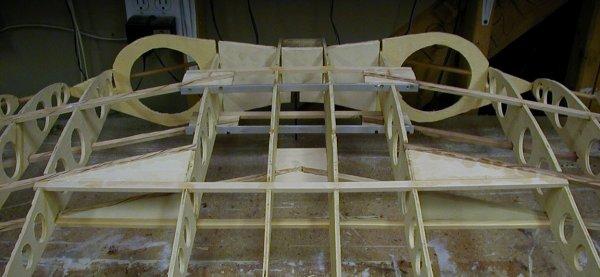
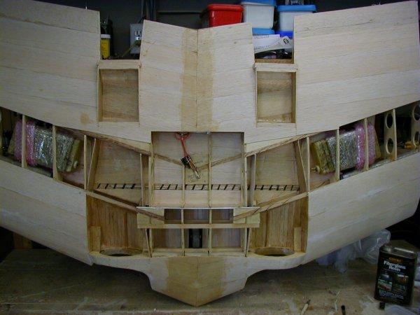
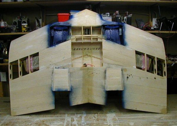
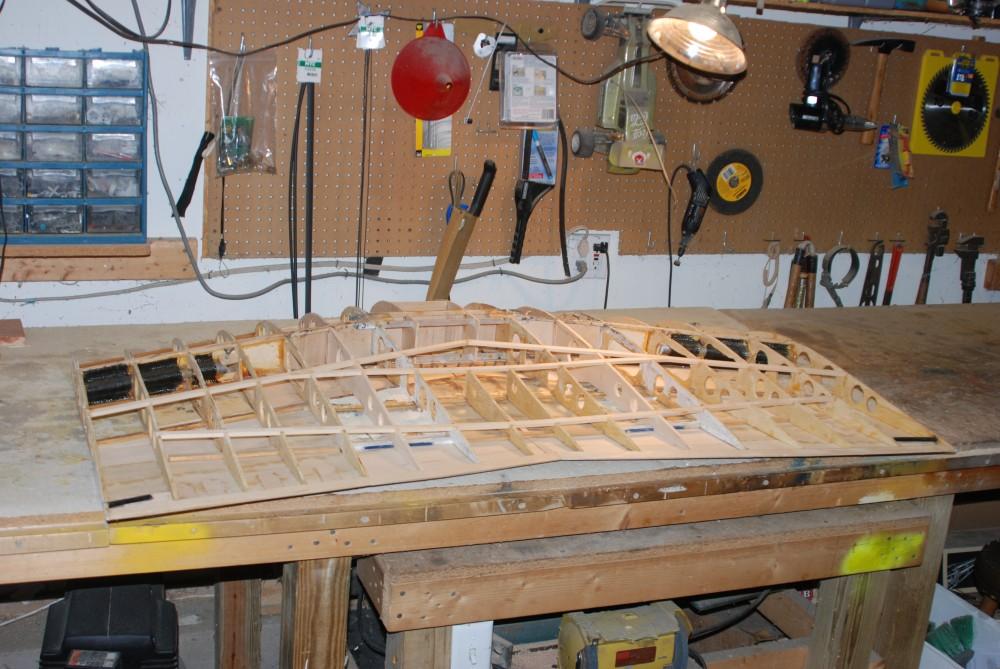
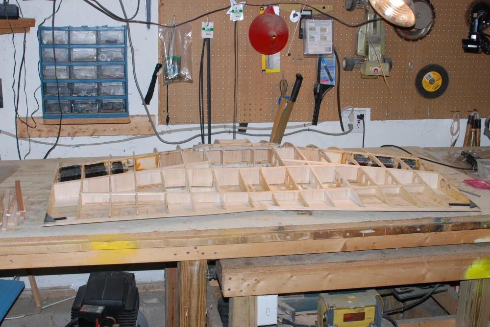
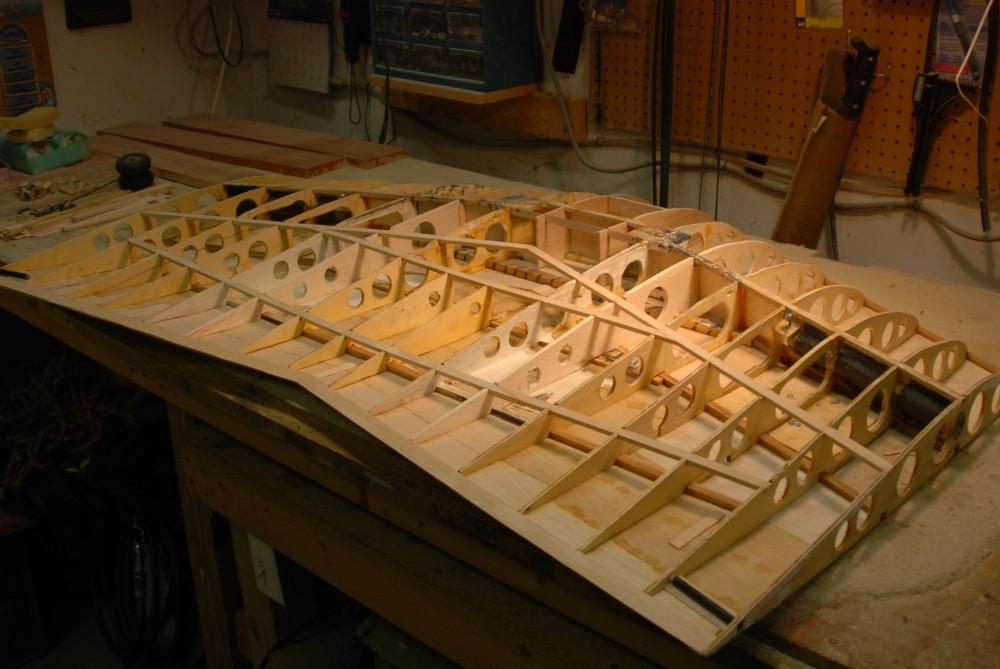
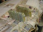
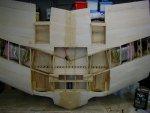
The bug-eyed monster continues to get framed. |

|
Another view of the center frame-up. |

|
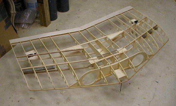
A detailed view of the center main spars. They are made of spruce, basswood, and
aluminum runners. |
|
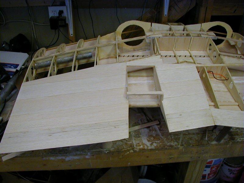
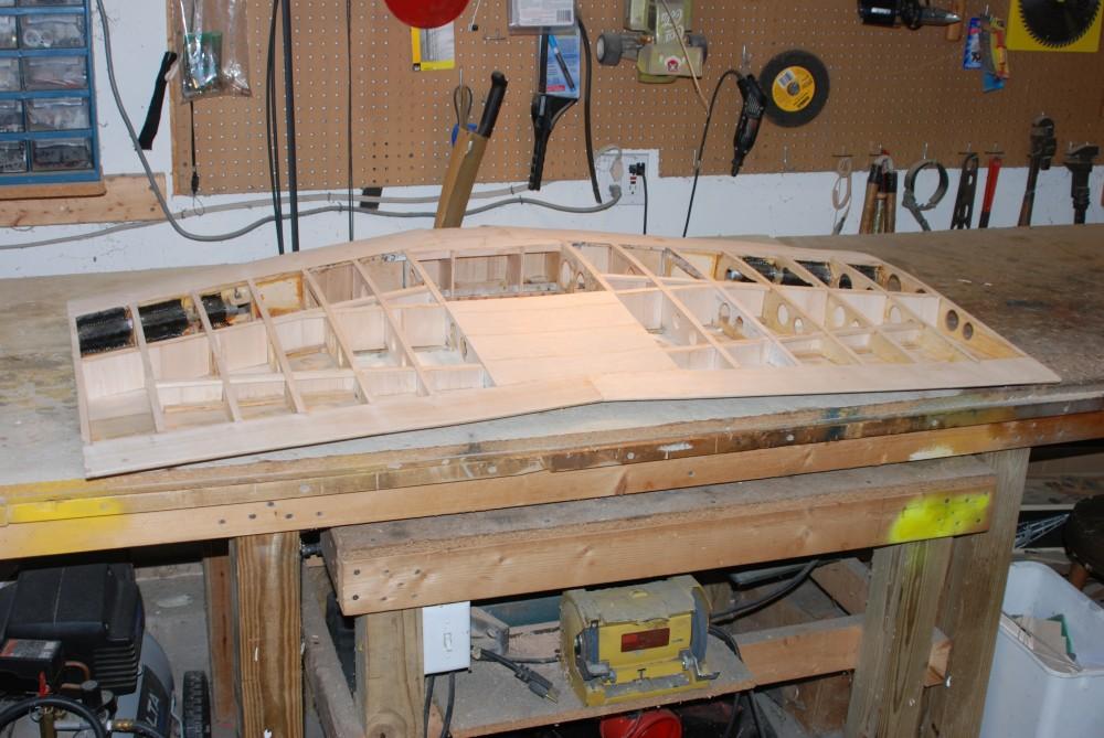
A view of the bottom sheeting partially completed. |

|
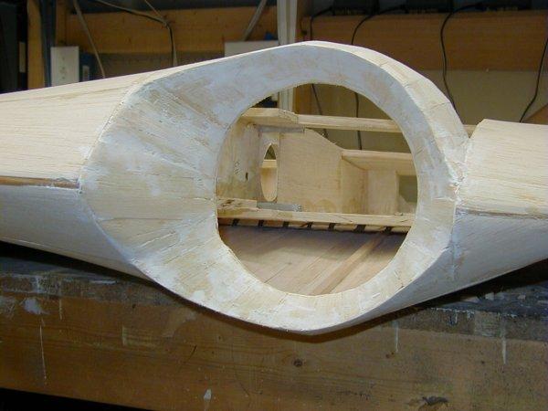
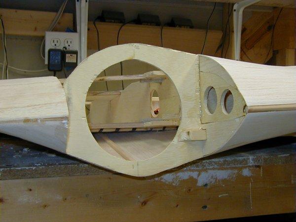
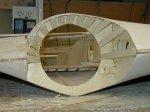
Left intake ducting complete. |

|
Right intake with no ducting. |
|
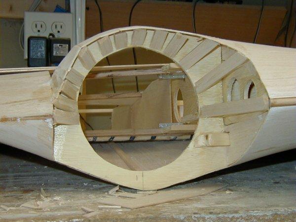
Right intake with some ducting. |
|
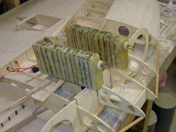
Home-made fuel tanks to go into wings. How to make tanks? Cut a foam core
to the size of your future tank. Wrap with fiberglass cloth. Use thinned (w/
alcohol) 30 minute epoxy as your resin and paint on with epoxy brush. DO NOT use
polyester resin - it will melt the foam and your mold with be gone. Wrap another
layer of cloth. Paint with thinned epoxy again. Repeat this wrapping and epoxy
layering AT LEAST five times. If you want to increase strength to internal pressure,
wrap after third or fourth layer with carbon fiber. Cut hole to fit fuel fitting and
epoxy correct sized keyring in place to strengthen opening. Pour acetone into
opening. This will dissolve the foam. Rinse a few times and you now have a
custom fuel tank. Check for leaks and fix any holes w/ fiberglass cloth and epoxy. UPDATE:
Don't build your fuel tanks like this! I built two tanks and left 15% nitro fuel in
one overnight. It ate away at the tank and leaked all the fuel over the inside of
the wing. The entire bottom sheeting was soaked and became warped due to the fuel.
I had to completely strip the covering off the bottom of the center wing section
and leave a fan blowing on it to dry the whole thing out. |
|
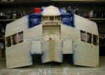
More sheeting complete. Intakes' ducting has been put in place. |
|
Next steps completed: internal ducting has been fiberglassed, fuel tanks have
been put in place, external fiberglass on center section. |
|
Top sheeting is in place over ducting and ducting has several layers of paint. |
|
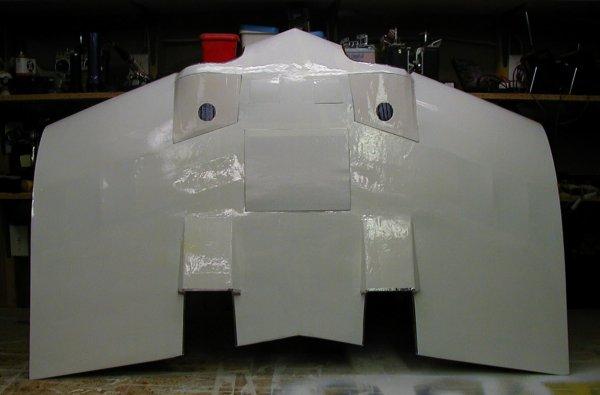
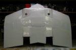
Center section is complete. White Monokote is in place and the engine hatches are
fiberglassed and painted with gloss-white. |
|
Another view of the completed center section. The Monokote seams at the ducting
intakes have been sealed with metallic hvac (heating - ventilating
- air conditioning) tape. This metallic tape is great
stuff - it conforms to any shape and the adhesive will stick to anything. The small
aluminum stick on the floor is a one foot ruler. |
|
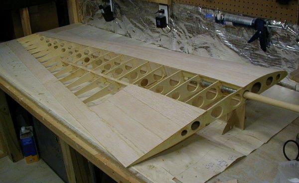
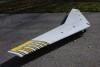
I have now gone back to the wing tips to finish them. Here is the left wing with
all sheeting in place. I still need to cut out the drag rudders and elevons, and add cap
strips. |
|
Drag rudder opening has been made,left elevon is done, and cap strips are in place. |

|
Here is the right wingtip with some sheeting. |
|
Here is the right wingtip complete with cap strips and the cutouts for the elevons and
drag rudder. |
|
All structure construction is complete. Now I need to cover the wingtips with
Monokote and add the engines and electronics. |
|
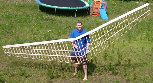
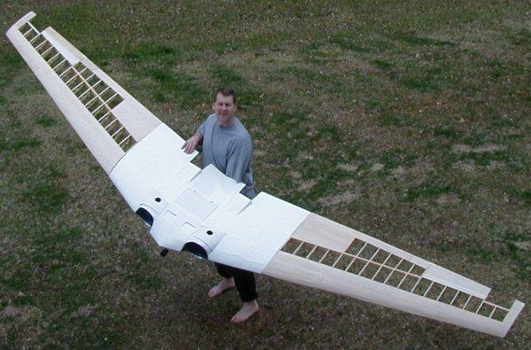
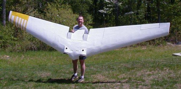
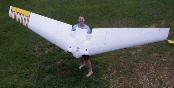
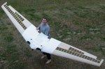
Me and my wing. The center section took almost three rolls of white Monokote.
The wingtips should take at least four more rolls. |
|
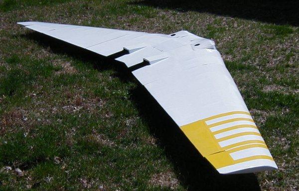
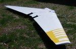
All Monokote is done. Each wing-tip took two rolls. The top of
the right wing-tip is yellow and the bottom of the right wing-tip is bright green in the
same pattern. I will be adding more detail to these yellow and green highlites on
the right wing-tip. All control surfaces are done, and the servos in the wing tips are in
place. |
|
Same stage as above. Now I have to add all the hardware in the center section. |

|
I have added the wing-tip highlites and most of the hardware, including the engines
and fan units, have been installed in the center section. All servos are in place -
now I have to wire everything up and install the battery backup circuits. The servos
will have two 5-cell battery packs and the receiver will have two 4-cell battery packs,
each with an automatic battery switch. |
 
|
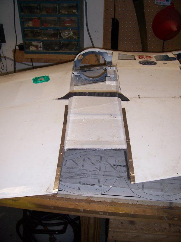
When I attempted to fly this in August and September 2006 on my club's
short runway, I found that there was not enough duct cross-area for efficient
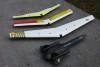
thrust. I modified the ducting. These two pictures show the original and new
ducting on the left side. |
|
These two pictures show the original and new ducting (under construction)
on the right side. |
|
And here are both ducts. |
|
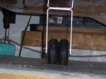
I also removed the retractable landing gear and put in double sets on all
three landing gear. |
|
I proved that the wing could fly on twin OS 91 VR-DF ducted fan power, but
those powerplants are very noisy, and I could only fly it at my club twice a year; the
special occasions where we get permission from the neighbors to exceed our noise
restrictions. |
|
So I decided to remove all the ducting, and rework the center section to
accept a large, quiet, 30 cc engine. |
|
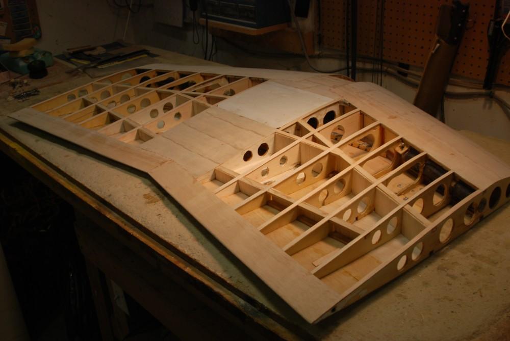
I stripped all the covering and sheeting off, reworked and repaired the
center section, and added extra spars and shear webs. |
|
I added new sheeting on the bottom, cap strips to the top, and re-sheeted
the front of the wing. |
|
The center hatch cover was reused, and the wing tip plug-ins were left
alone, so the wing tips were not modified at all. |
|
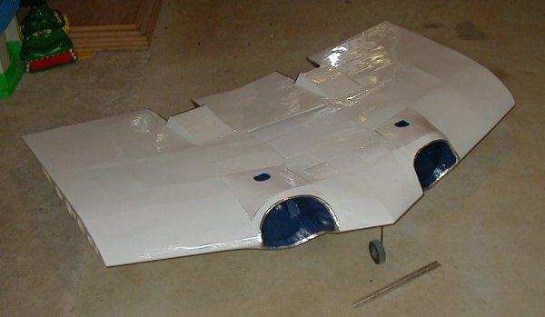
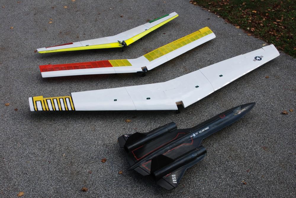
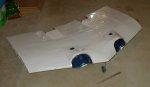
Finally, the center section was recovered with white Monokote, and it is
now waiting for the right engine. It is a much smoother, cleaner looking airplane
now. Here is a photo of all three of my big wings with my 102" long SR-71
Blackbird for comparison. |