UAV Airframe Development Stages
Stage 1 - Flying Wing Prototypes
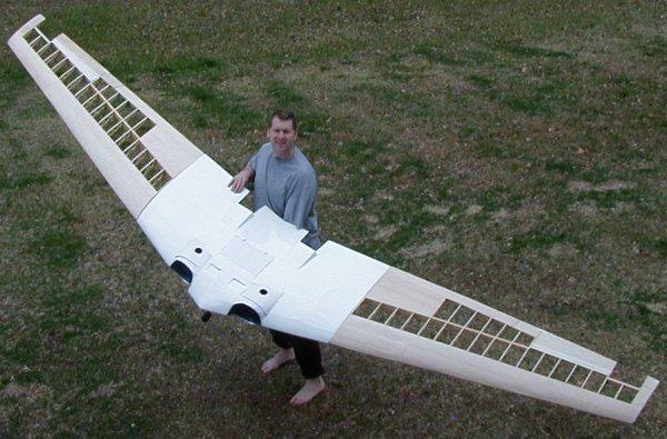
I have been building wings and flying them for over 12 years. These are all remote-control aircraft. Pitch and roll are controlled by elevons. My 11 foot wingspan Klingberg wing was modified to include drag rudders as a testbed for the full size UAV drag rudders. The full details on that are available below.
Stage 2 - Testbed Aircraft - 11 Foot Flying Wing
|
|
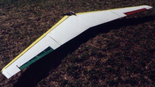
This aircraft has been flying for 10 years and has
flown in four states and at two AMA open houses. It was based on the Klingberg
flying wing, which was based on the Northrop N-9M/XB-35/YB-49. It has no vertical
surfaces. Until 1998, it had no yaw control. When I completed the initial design for
the final UAV aircraft, I realized I needed a testbed aircraft for the drag rudders.
These required quite a bit of thought to enable them to open and close correctly. A servo
was added to each wingtip and split-opening drag rudders were installed. The
standard way to install control surfaces is to have them move in two directions from a
neutral center point. However, I did not want half open drag rudders at neutral, and
then fully opened and fully closed drag rudders at full servo throw. I needed them fully
closed at neutral and fully open at left and right full rudder. It required the drag
rudders to open on only half servo throw, while the other half of the servo throw did
nothing. I was able to accomplish this with internal push rods,rubber bands to close
the split rudders, and freely moving linkage for the half of the servo throw that was in
the opposite direction for each wing tip. Note: This was done before I had
any computer radios. I now have JR 8103 computer radios which eliminate the need for
this mechanical mixing, but this setup can still be used for simple non-computer radios,
or to lower the number of channels needed.
|
|
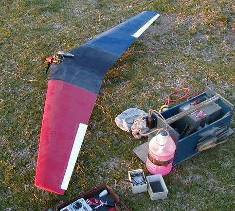
Take a look at these pictures for a better view of the elevons and drag rudders. On the left is full up elevator with the drag rudder closed. On the right is full down elevator with the drag rudder fully open. In addition, a rate gyro is installed in the center of the wing in the yaw axis to help smooth out yaw oscillations.
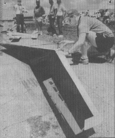
| This big Klingberg Wing is famous. Here is the article that appeared in the Dayton (Ohio) Daily News on 9 June 1991. The image and text are thumbnails; click on them to see full size. |
|
Stage 3 - Airfoil selection and analysis for UAV
 |
 |
The left image is a cross section of the Eppler 334 airfoil. I chose the Eppler 334 for two main reasons; it was designed specifically for flying wings with no tail surfaces, and it has the highest coefficient of lift at low Reynolds numbers in the Eppler flying wing airfoil series. The right image is the graphical output of my Panels program which uses the source panel method to determine pressure coefficients of any airfoil. It is a thumbnail, so click on it to see the full size image. The source panels method sets up a system of equations that relates the geometry of each separate section to a pre-determined angle of attack, taking into account the entire airfoil and all the surfaces nearby. Those other surfaces may be another airfoil, such as in abiplane or canard configuration, or a flat surface like the Earth to determine ground effect. Click here to see the system of equations that Panels created and solved for this pressure coefficient distribution around the Eppler 334 airfoil. This airfoil and others are available from airfoils.zip on my Software Page.
Stage 4 - Half Scale Flying Wing Construction
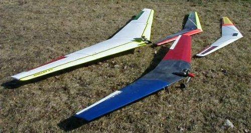
This was an 8 foot wingspan (1/2 full scale) prototype aircraft built to show that the proposed airframe is flight worthy. It was a semi-scale Northrop N-9M flying wing. It crashed in June 2002. This aircraft had these modifications from a true N9M:
|
I had originally built this as an electric plane, but converted its power source to an OS 46 two-stroke r/c engine. |
21 October 1999 Update: First flight of the prototype! Off to the flying field (parade field a Fort Meade, Maryland) and fire the engine. While checking the mixture, I held the plane up and it tried to climb straight up out of my hands. It has a thrust to weight ratio of greater than 1:1 at full bore. I had kept the first test flight center of gravity well ahead of the design position just to be safe. It required full up trim and a little back pressure on the stick to maintain level flight. As I move the CG back, this should be eliminated. Take off roll was straight and true and the plane flew very smoothly. Turns were precise and very little adverse (swing) yaw was noticed. It maintained level flight at just above idle throttle setting - power is not a problem. Full throttle allowed the plane to climb vertically. I had originaly installed micro servos on the elevons for electric flight, but will have to refit standard servos if I want to enlarge the flight speed envelope. I experienced no flutter or servo gear stripping, but I purposefully kept the speed slow for the first flight. More updates to come as it makes more flights.
|
08 Mar 2000 Update: The icy grip of winter has loosened its hold... Off to the flying field for the first flight off of grass. I also moved the CG back a bit by placing the receiver battery as far back as it would go in the radio compartment. No problem- the wing is overpowered and it jumped off the ground. I tried a few loops and flew several circuits of the field. |
|
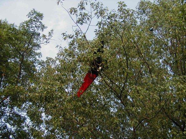
Jun 2002 Upate: Plane go boom! I'm not quite sure what happened, but the plane was flying very nicely until it decided to fly away by itself. It was almost as if the elevon servos center points were slowly moving; the plane started to pitch nose down and I add back stick, it returned to level flight but immediately pitch nose down again, I added more back stick until I was finally at full back stick and full up trim, but the plane descended slowly out of straight and level flight under full power into the top of a tree about 1/3 mile from the field. I was trying for an open field and managed to catch the top of the very last tree before the field. It may have been radio interference, but everyone who crashes an RC plane says that. The airframe does fly very well though. |
Stage 5 - Full Scale Flying Wing Construction
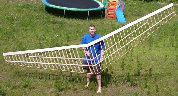 |
 |
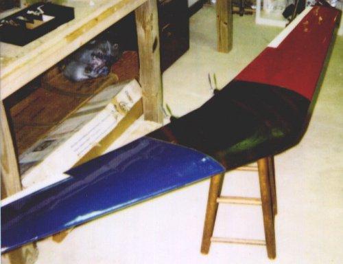
The final aircraft is a 16 foot wingspan version of the prototype aircraft powered by two OS 65 VR-DF ducted fan engines with Turbax III fan units. Because it is a ducted fan with the engines buried in the wings, it resembles the Horten HO-IX (HO-229) flying wing. There is no beaver-tail like the HO-229 however. It has retractable landing gear and drag rudders. This aircraft has these further modifications from the half scale proof of concept aircraft: