Several of these projects include a PIC 12C508 as the
brains. The source code for each project is included, and the pinouts
for the PIC are listed in the comments in the source code for each
project. See my PIC
development page for links to the necessary PIC compiler and PIC
programmer software packages, both of which are is free. All you will
need to buy is an inexpensive PIC programmer interface which connects to
a serial port on your computer, and of course the PIC, wiring,
resistors, and capacitors that make up each project.
NightOwl - Stabilizing 3-Axis Gyros
with PIC 12C508 mixer
NightOwl versions 4 and 5 each have a 3-axis rate gyro stabilizer.
There are four control surfaces on each NightOwl. Two horizontal
surfaces move together and control pitch. Two vertical surfaces
move together and control yaw. All four surfaces move together and
control roll. The gyro stabilizers installed to versions 4
and 5 of the NightOwl are made from disassembled HK 401B rate gyros.
These photos shows the gyro and mixer setup for NightOwl version 4.
Three HK 401B gyros were taken apart, removed from their original
boxes, and hot-melt glued together into a smaller package with each gyro
rotated to the correct angle for its sensing axis. Gyro #1 senses
roll, gyro #2 senses pitch, and gyro #3 senses yaw. The outputs of
each gyro is routed to mixers. The first mixer is used for the
horizontal control surfaces, for roll and pitch. The second mixer is
used for the vertical control surfaces, for roll and yaw.
Rx aileron output --> roll gyro --> roll stabilized PWM
Rx elevator output --> pitch gyro --> pitch stabilized PWM
Rx rudder output --> yaw gyro --> yaw stabilized PWM
roll stabilized PWM + pitch stablized PWM --> mixer #1 --> left
horizontal surface + right horizontal surface
roll stabilized PWM + yaw stabilized PWM --> mixer #2 --> top vertical
surface + bottom vertical surface
NightOwl version 5 was actually the first NightOwl to receive stabilization
with gyros. Because of the inherent slight variability of the
timing circuits in all gyros, the use of three HK 401 gyros meant that
the input to the mixers would slowly walk apart from each other, as each
gyro's timer was not EXACTLY the same as the other gyros. The timing oscillator output on one gyro was connected
to the other two gyros, and their timing oscillators were disconnected
and overridden. This kept all three gyros on the exact same timing, and
allowed the output of the gyros to be connected into two standard
commercial mixers, which are the yellow objects in the photo.
NightOwl version 4 received special home-made mixers were made from PICS with custom
code that ignored the inherent timing problems that occur with separate
timing circuits in independent gyros. This required that one
mixing input come from a gyro set to high-speed digital output at 3 ms
frame rate, and one mixing input come from a gyro set to normal speed
output at 20 ms frame rate. The 20 ms frame rate was the master
for input, and was also used for the output frame rate. The PIC source code for the timing independent mixers is here.
Both versions worked great; these separate setups were done to test
if both methods would work.
A final, smaller version of stability was completed on both NightOwl #4
and #5 via the use a
3-axis gyro stabilized receiver from Hobby King.
The outputs of the receiver, already having gone through the receiver's
internal gyro on each axis, are fed into the same commercial mixers
originally used for NightOwl #5. Because all three internal gyros
are already on the same timing circuit, no additional modifications are
needed.
This reduced the components from (receiver + 3 gyros + 2
mixers + special wiring : on the right in photo #2) to (receiver + 2 mixers
+ less wiring : on the left in photo #2). If you want to
build a similar aircraft with three control surfaces (two elevons and a
single rudder), as NightOwl's #1 through #3 were configured, you could
even eliminate the 2 mixers, as the 3-axis stabilized receiver has the
built-in ability to control elevon aircraft.
PIC 12C508 Drag Rudder Controller
The PIC reads the rudder PWM output from the receiver, and extracts out the
left and right commands to send to the separate servos on each wing tip. 1000
μs- 1500
μs = left rudder, 1500
μs - 2000
μs = right rudder. Since the left drag
rudder only needs to move for left rudder command, and vice versa for the right
rudder command, the PIC code translates all of this to individual commands for
each servo. The PIC source code
for the drag rudder controller is here.
1000
μsto 1500
μs --> left yaw command from receiver
2000
μsto 1500
μs from Rx = no left command --> PWM output =
1000
μs to
left drag rudder servo
1500
μs from Rx = no left command --> PWM output = 1000
μs to
left drag rudder servo
1500
μs
to 1000
μs from Rx = increasing left command
--> PWM output = 1000
μs - 2000
μs to left drag rudder servo
1000
μs from Rx = full left command --> PWM output = 2000
μs to
left drag rudder servo
1500
μs to 2000
μs --> right yaw command from receiver
1000
μs to 1500
μs from Rx = no right command --> PWM output = 1000
μs
to right drag rudder servo
1500
μs from Rx =
no right command --> PWM output = 1000
μs
to right drag rudder servo
1500
μs to 2000
μs from Rx = increasing right command
--> PWM output = 1000
μs - 2000
μs to right drag rudder servo
2000
μs from Rx = full right command --> PWM output = 2000
μs to
right drag rudder servo
PIC 12C508 Servo PWM Driver
The PIC reads three momentary pushbuttons as inputs, and drives three
outputs: a PWM for the servo, and two LEDS for status. The PIC starts at
1500
μs output, and has 100 positions available for output from 1000
μs to 2000
μs. One pushbutton increases the output by 10
μs, and one
pushbutton decreases the output by 10
μs, with safety bounds at 1000
μs and 2000
μs to avoid overdriving the servo. The third
pushbutton puts the PIC into status display, with one LED showing the current
PWM / 10, and the second LED showing the single digit remainder, starting
at 1000
μs. The PIC
source code for the servo driver is here.
Example of status display:
At 1000 + 0010
μs (1.000 ms), push the status button and the LEDs will flash : #1 for 0 flashes,
#2 for 1 flash.
At 1000 + 0590
μs (1.590 ms), push the status button and the LEDs will flash : #1 for 5 flashes,
#2 for 9 flashes.
At 1000 + 1000
μs(2.000 ms), push the status button and the LEDs will flash : #1 for 10 flashes,
#2 for 0 flashes.
HK Multi-Copter 2.1 Flight Controller
The HK 2.1 rate gyro board was one of the first purpose-built boards
designed for multicopters. Before these simple rate boards, multicopters were
stabilized by independent rate gyros set up on separate axis and controlling
separate ESC or servos, directly or via mixers. These boards have since been made
obsolete by the newer HK KK 2.0 and later flight controllers, but they still
work fine for other uses.
OpenAero software 1.14.1
is available to install to these boards, and this software allows them to act as
3 axis rate gyro stabilizers. The source code is
available
here.
One modification I made to the stock OpenAero firmware was to increase the required timeout period before entering
programming mode via the optional LCD. This default period was about 2 seconds, which would
enable the programming option. During acrobatics, it is possible to
command the correct combination of stick inputs to get into this mode, which
disables outputs. I discovered this accidentally while flying an acrobatic
plane through a series of snaps. I just happened to hit the correct stick
combination and held it for more than 2 seconds. Once the controller had
entered programming mode (unknown to me), the plane kept the same control
outputs and snapped up, over, and down, right into the ground. I increased the timeout to 20 seconds
so this would never happen again. The source software can also be compiled for various wing types: normal, flying
wing, and flaperons. I have a flying wing version
with the programmable period bumped to 20 seconds in one of my flying
wings for stability. Take a look at the source code and experiment with
possibilities; many other modifications can be done.
Draganfly FET Interface with PIC 12C508
The original Draganfly quadcopter and its control board have been around for 20+ years. It
uses three rate gyros, a custom circuit board with a PIC running custom code, and
four FETS to drive four brushed motors. It was expensive, but it was all
that was available to fly commercially for a long time. You can get orders
of magnitude more performance now out of inexpensive brushless motors, BESCs,
and off the shelf flight controllers,
but it is still fun to play with these older electronics.
Experimenting with this hardware, I traced the wiring on the board
and O-scoped the inputs to the FET gates to see the range of signals
they receive. The PPM pulses going to the FETs last from 0
μs to
5800
μs. It was a simple matter to solder onto that connection, and
use a PIC to scale the 0
μs - 5800
μs pulse to a standard 1000
μs - 2000
μs
PWM pulse that is used to control servos and ESCs. I built four of
these converters and tested them to drive four servos from the Draganfly
board.
I then used the Draganfly board and the converters to drive
brushless ESCs and motors on a home-made quadcopter of similar size to
the Draganfly. This worked fine electronically, but the gains were
vastly different between the original brushed Draganfly setup and the
brushless setup of the new quadcopter. A modification to the code
in the PIC converters would allow variable gains (scaling of 0
μs -
5500
μs --> 1000
μs - 2000
μs) via a separate PWM input, but I have not gone
back to make that addition to the code yet. It is still something
to be done when I have the time. The original Draganfly board and
converter board with four PICS, mounted to a simple frame, is shown the
first photo. The original Draganfly frame with its brushed motors, and
the new brushless motor frame with the adapted electronics is shown in
the second photo.
Hextronic/TowerPro Mag8 15-18A ESC with SimonK
firmware
There are several version of this ESC, with two different combinations of
FETs: pFETs + nFETS,
or just nFETs, and different clock sources: 16 MHz external, 8 MHz
external, 4 MHz
internal. I traced the ATmega8 pinouts to
each set of FETs on the Mag8 version that I own, but none of the definition files for the SimonK Mag8
alternatives ( tgy.inc, tgy6a.inc,
tgy_8mhz.inc,
tp.inc /
tp_8khz.inc /
tp_nfet.inc) matched these versions of Mag8s that I own
for pinout to FETs or the external 16 MHz oscillator present. I figured
I would have to make my own definition file and compile a special version of SimonK
firmware for my Mag8 ESCs. However, after more searching, I found that the
rct50a.inc and
tp70a.inc
FET
definitions matched my Mag8 for pinouts, with the low side FETs inverted
for TP70A. Both also specify a 16 MHz clock. The analog input channels
(PC2/ACD2, PC3/ADC3, PC4/ADC4) to read the back EMF from each motor phase, the main voltage
input (PC7/ADC7), and the PWM input on PD2 also match the connections on this
version of the Mag8. The Mag8 ESCs that I have use a separate
daughterboard for the 5V BEC, which is three 7805 voltage regulators wired in
parallel. I have removed the BEC from these ESCs to save weight, since the
5V supply is not needed for the multi-rotors to which I have installed these
ESCs. These photos show the top and bottom of the ESC with the 5V BEC
daughterboard removed.
TP70A.inc definitions for ATmega8 pinouts:
; PORT D definitions *
;*********************
.equ ApFET = 7 ;o
.equ c_comp = 6 ;i common comparator input (AIN0)
.equ AnFET = 5 ;o
.equ BnFET = 4 ;o
.equ BpFET = 3 ;o
.equ rcp_in = 2 ;i r/c pulse input, opto-coupled, needs pull-up [This 18A Mag8
is not opto-coupled like the 70A version, but this does not impact the code
execution.]
.equ CpFET = 1 ;o
.equ CnFET = 0 ;o
; PORT C definitions *
;*********************
.equ mux_voltage = 7 ; ADC7 voltage input (44k from Vbat, 2.0k to gnd, 10.45V in
-> .448V at ADC7)
;.equ = 6 ; ADC6
;.equ = 5 ; ADC5
.equ mux_c = 4 ; ADC4 phase input
.equ mux_b = 3 ; ADC3 phase input
.equ mux_a = 2 ; ADC2 phase input
;.equ = 1 ; ADC1
;.equ = 0 ; ADC0
The TP70A version works in these ESCs; Hextronic must have wanted to use the same firmware in different ESCs, so they
made the ATmega8 pinouts the same between the original version of the Mag8 15-18A and
the TowerPro 70A ESCs.
The faster update via OneShot125 and better ESC control inherent in SimonK allows for much higher gains on the multi-rotors with Mag8 ECS with
SimonK firmware.
Updating these ESCs from stock firmware to SimonK firmware made the difference
between an unstable multi-rotor and stable multi-rotor with the exact
same PID gains.
Lemon Telemetry Receiver with RSSI + HobbyKing
E-OSD with updated firmware to display RSSI
Lemon Telemetry Receiver with RSSI (LM0051 / LM0052)
- LM0052 receiver includes altitude sensor with altitude & variometer
(climb/descent rate), receiver voltage, RSSI - all sent via telemetry to ground
- LM0051 does not include the altitude sensor & variometer
- additional telemetry supported :
- main battery pack voltage + main battery pack current - needs connection
to Lemon V/I sensor; need to calibrate this connection
- main battery pack voltage only - needs connection to main battery
pack positive lead; need to calibrate this connection
- temperature - needs temperature sensor
Set switch on DX9 for altitude voice readout.
Set switch on DX9 for main battery pack voltage voice readout.
Set switch on DX9 for Rx voltage voice readout.
Set alarm on DX9 for low main pack voltage.
Set alarm on DX9 for low receiver voltage. This receiver needs 4.5 volts
to function, so set the alarm level a little higher, at 4.7 volts. ESC BEC
output should
always be at 5.0 volts.
Set audio tone on DX9 for variometer report; you can set the up and down rates
in ft/sec where tones will start.
- RSSI (received signal strength indicator) is down-linked via telemetry, and
is also output at the receiver via an analog pin
with 0-3V range = 0 - 100% RSSI
HOWEVER (!), the RSSI value down-linked in the telemetry stream is NOT
displayed as RSSI; it is displayed as FlightLog - A, which is signal strength for the
main receiver. This is annoying, as there is no way to set up an audible
alarm on the DX9 for FlightLog - A, while an audible alarm can be set for RSSI.
I confirmed this with the latest Spektrum firmware Airware version installed to
my DX9 as of July 2020.
I contacted Lemon about this in July 2020. The response was that Lemon had
implemented RSSI before Spektrum had added RSSI to the Spektrum telemetry stream, so
Lemon used the best available data field at the time, which was FlightLog - A. When Spektrum added
RSSI to Spektrum receivers, they included RSSI in a different data field labeled
'RSSI', and
enabled the alarms on Spektrum transmitters on that new field. Lemon plans
to release newer versions of their RSSI receivers, and will be putting RSSI into
the same data field that is used by Spektrum. With these new Lemon
receivers, the same low RSSI alarm will be able to be programmed on Spektrum
telemetry-enabled transmitters, as can be done with Spektrum receivers.
Set audio alarm on DX9 for low RSSI. - cannot be done yet,
Lemon-reported RSSI not a valid telemetry audio option (!) from V1 receivers
Set switch on DX9 for FlightLog-A voice readout. - cannot be done yet, Lemon-report
RSSI not a valid telemetry voice option (!) from V1 receivers
These photos show the E-OSD with the 6 pin ISP connections on the E-OSD.
I had a spare board and just wired them with the same pinout that is used by a
USBASP. The videos show flights on 26 July 2020 and 7 August 2020 at the RCMB flying field
with this setup in a 5' flying wing.
The new firmware is flashed with the application AVRDude, which is available
for Windows, Linux, Mac. AVRDude can be used to flash many ATMega chips on
Arduinos, ESCs, flight controllers.
This assumes you have the two files to flash located in the same directory as
AVRDude. The individual
command line options are:
-P usb -c usbasp (port = usb, programmer = usbasp)
-p ATmega88P (CPU =
ATmega88P)
-v
(verbose output to display everything - this is useful for debugging problems,
but not mandatory)
-e (erase; need to toggle everything to 0 before writing)
-U flash:w:cl-osd.hex (write to flash
memory,
"cl-osd.hex" is the executable)
-U eeprom:w:cl-osd.eep (write to eeprom
memory,
"cl-osd.eep" is the eeprom memory - this is the character set / font used for the video
overlay)
You MUST write both files to the ATmega88P, because the executable relies on the
character set as the display font.
Once the new firmware has been flashed to the E-OSD, you connect video, main
battery pack voltage, and the 0-3V RSSI voltage from the Lemon receiver to the E-OSD. Main voltage
goes to battery input #1 and RSSI voltage goes to battery input #2.
To display RSSI as an overlay in video downlink, you need to calibrate low and high RSSI voltage
values.
If you wish for the main battery pack voltage to flash at a low level, you need to calibrate low voltage value
for that flashing alarm.
Calibration of each of these values is explained here: https://www.rcgroups.com/forums/showpost.php?p=26238951&postcount=3213
HobbyKing Orange UHF 915 MHz and 433 MHz Long Range Datalinks
using OpenLRSng software
The photos to the right show
all the modules I originally purchased on which
to
experiment when HobbyKing had a good sale.
I replaced the stock
whip antennas with home-made dipole
antennas on everything except for the 915 MHz
transmitter, which has a FrSky Super 8 antenna.
These various modules have RF output power
levels that range from 100 mw to 1 watt,
depending on the transceiver module and supply
voltage. Details on how to build the
homemade receivers are below.
I have two Orange 9ch receivers that were both
originally 433MHz receivers. Those two receivers are shown in the top photos on
the right, and they use the
RFM22B transceiver,
which is rated at 100 mw RF maximum output. I swapped the RFM22B 433MHz RF modules for
RFM22B 915MHz RF modules, and re-flashed the ATmega328P processors with 915 MHz receiver firmware.
As of February 2020, HobbyKing was selling the
Orange 9ch 433 MHz receiver for $13.
The
RFM22B 915 MHz RF modules
can be found on eBay for about $7 shipped.
After a little soldering, that gives you a small, long range 915 MHz receiver with RSSI
and telemetry for $20.
915 MHz Range Tests:
During a flight test in April 2021 using the
Orange 915
MHz transmitter with a Super 8 antenna, and an
Orange 915 MHz transmitter modified to be a
receiver, with a homemade 915 MHz dipole antenna, the wing reached 1950 feet altitude
and 1551 feet ground range, for a total line of
site distance of 2491 feet. The received signal
strength indicator (RSSI) was 73% at this point.
During a second flight test in April 2021 using the
Orange 915 MHz transmitter and a homemade 915 MHz receiver with the RFM22B transceiver module,
with the same antennas as above, the wing reached 1463
feet altitude and 1213 feet ground range, for a
total line of site distance of 1900 feet.
The received signal strength indicator (RSSI)
was 68% at this point.
During a third flight test in April 2021 using the
Orange 915 MHz transmitter and one of the Orange
9ch receivers, which I had converted from 433 MHz to 915 MHz,
with the same antennas as above, the wing reached 1530
feet altitude and 757 feet ground range, for a
total line of sight distance of 1707 feet.
The received signal strength indicator (RSSI)
was 71% at this point.
I had both Orange 915 MHz and 433 MHz
equipment, but sold the 433 MHz gear after I
decided to use just the 915 MHz frequency.
1. 433 MHz Tx, RFM23B @ 6V [1 watt],
Orange Tx with 6V
DC-DC converter & capacitor added, homemade
dipole antenna
2. 433 MHz Rx, RFM22B @ 3.3V [100 mw],
Orange Tx
converted to receiver
(#2, top picture to the right)
3. 433 MHz Rx, RFM22B @ 3.3V [100 mw], Homemade Rx built with RFM22B +
Arduino Pro Mini +
3.3V regulator
(#3 to right)
4. 433 MHz Rx, RFM23B @ 3.3V [400 mw], Homemade
Rx built with RFM23B +
Arduino Pro Mini +
3.3V regulator
(#4 to right)
Details on #2 @ 433 MHz:
The older version Orange 100 mw 433 Mhz transmitter module
was configured as a receiver. The
Orange 100 mw transmitter / receiver module also uses the RFM22B transceiver, so
it has a 100 mw maximum RF output, which is powered by the built-in board regulated 3.3 volt
power supply. This is the same overall physical size Orange module as the 1 watt version,
but includes the lower RF power RFM22B transceiver on the main board.
During a flight test in November 2020 using the
433 MHz equipment and homemade 433 Mhz dipole
antennas at each end, the wing
reached 1422 feet altitude and 1407 feet
ground range, for a total line of
site distance of 2000 feet.
The received signal strength indicator (RSSI)
was 65% at this point.
915 MHz transmitter module with Super 8 Antenna,
installed to JR XP8103 radio
433 MHz transmitter module with home-made dipole
antenna,
installed to JR XP8103 radio
915 MHz transmitter module with Super 8 antenna,
915 MHz receiver module with JST power input
and PPM signal output leads
The Orange Open LRSng transmitter module's
hardware for each frequency is identical, except for the
HopeRF RFM23BP transceiver which is tuned to 433 MHz or 915 MHz.
Open LRSng software also supports the RFM23BP
868 MHz transceiver, if you want to operate in
that band.
They are listed as having a 1 watt RF output,
but these “1 watt” transmitter modules do
not really provide 1 watt RF output in their
stock configuration. The voltage regulator
on the board only supplies 3.3 volts to the RF
transceiver, which then provides an RF output of
around 400 mw. That RFM 23BP transceiver
is rated at 1 watt RF output at 5.5 to 6 volts input,
so the only way to get 1 watt RF actual output
is to
bump up the voltage input
to between 5.5 to 6 volts.
You have to be careful how you do this, because
other components on the board will get fried at
5.5 volts. I have added an adjustable DC-DC
converter set at 5.5 volts, with a large capacitor to
keep a smooth supply. This 5.5 volts goes
just to the RF section of the transceiver module,
isolated from the rest of the board.
This DC-DC converter and capacitor are protected
in shrink wrap, and sits inside the transmitter
module, shown to the right. You can see
the power input to the RF section on the red
wire in the bottom center of the photo. That
trace which now has 5.5 volts running to it has
been cut on the board to isolate the RF
transceiver
power from the rest of the board. The
built-in 3.3 volt regulator powers everything on
the board, except for the RF section of the
RFM23B transceiver, which is powered at 5.5
volts from the added DC-DC converter.
I
have several additional Orange 1 watt 915 Mhz transmitter modules configured as receivers,
having re-flashing them with Open LRSng 915 MHz “use transmitter as
receiver” software.
Leaving the 3.3 volt power supply unaltered on the
"receiver" modules for simplicity sake, they are
good for about 400 mw downlink, but still provide
very long range telemetry and include RSSI.
The
"receiver" modules are wired to accept 6 – 12
volts input on a JST connector, and provides PPM
output on a standard 3-pin servo connector.
These external power and PPM connections are shown
above to the right, and the internal wiring connections are
shown directly to the right.
White = PPM out, Red = 6-12 volts power in,
Black = ground.
There is normally a transistor controlling the
built-in buzzer on these "receiver" modules.
The
pin from the ATmega328P processor that controls
the buzzer is also the one pin
that can supply PPM output, so you have to de-solder
that transistor if you don't want the buzzer
running all the time when PPM is output on that
pin. I run this PPM signal to a flight controller
running iNav software.
I have the transmitters and receivers bound to
each other, and they hop across
several frequencies near 433 Mhz and 915 MHz. I have flown this equipment in a large flying wing out to
several thousand feet, verifying the RSSI stayed high throughout the flights. I
have tested this with the 433 Mhz ground antenna set vertically, the 915 MHz
ground antenna set both vertically and
horizontally, and the air antennas
set both horizontally and vertically (not that that really matters much for a
plane pitching and rolling). I did not notice a
large difference in reported packet drops, which
are reported audibly by the transmitter module
based on the downlinked telemetry RFFI status
from the airborne unit.
The 433 MHz antenna and flight controller
installation is shown here to the right. The actual 433 MHz
receiver is in the wing, above the flight
controller in this photo.
Homemade OpenLRSng Receiver
You will need an Arduino Pro Mini running at
16 Mhz, and an RFM22B or RFM23B UHF module at 433 Mhz, 868 MHz,
or 915 MHz; whichever frequency you are using. The pinouts on
the RFM22B and RFM23B are the same. The RFM22B is powered
at 3.3 volts and provides 100mw (20 dBm) of RF output power.
The RFM23B is powered by 3.3 to 6 volts and provides up to 1
watt (30 dBm) of RF output power. While the RF portion of
the RFM23B can be powered by more than 3.3 volts, the digital
control pins MUST be powered at 3.3 volts, so the Arduino Pro
Mini that controls the RFM23B must be powered at 3.3 volts, so
that its digital outputs will be at 3.3 volts. If you
power the Arduino at 5 volts, it will send digital control
signals at 5 volts, which will degrade and damage the control
circuitry of the RFM23B. If you want the full RF power of 1 watt from
the RFM23B, it must be powered at 5.5 to 6 volts, but again,
only the RF module can be powered by more than 3.3
volts - the controlling CPU must be powered by 3.3 volts so the
digital IO it sends the RF module is at 3.3 volts.
I have built homemade UHF
receivers with the RFM22B
module. The first step was
tracing the circuitry of the
hardware I wanted to copy, which
was the Orange 1 watt
transmitter module. This module
is basically an Arduino Pro Mini
at 16 Mhz and a RFM23B radio
module, but I wanted to keep it
small and I had RFM22B hardware.
Since the pinout is the same
between the two RF modules, the
RFM22B drops right in place of
the RFM23B. I built the
first receiver on a breadboard
to test the wiring, and then
shrunk it down to a small size,
just slightly larger than the
Arduino Pro Mini. You can
see the required connections
from the radio module to the
Arduino to the right.
Those connections are:
You also need to connect GPIO0
to RXON, and GPIO1 to TXON. You
can see those two loop-back
connections on the schematic,
both on the RFM22B or RFM23B
module. Those connections are
managed by the code running on
the Arduino. Power is provided
via GND and 3.3 volt
connections, and PWM output
comes from the Arduino Pro Mini
connection DP10 - pin 10.
I made a
printed circuit board
(PCB) to hold the RFM22B module
and fit the
breadboard for the initial
testing. You can make this
PCB at home,
which you etch with ferric
chloride. You draw the
circuit on the board with a Sharpie marker, and drop it in
the ferric chloride etching
solution. The ferric
chloride will dissolve the
copper off the board and leave
behind the copper protected
under the Sharpie marking.
Remove the etched board from the ferric chloride
and then
clean the Sharpie marking off
the board with acetone,
and you have your very own homemade
PCB.
Once I had the wiring and
connections confirmed with
the breadboard version, I took
the Arduino Pro Mini (first
photo to the right) and ran the
required connections to a new
PCB (second photo to the
right), made for the final
shrunken down version. This
new small PCB holds the
RFM22B module and simple power
supply via a 3.3 volt linear
regulator. This board is
attached to the back of the Arduino
Pro Mini using just a few pins
to connect the two boards.
The final receiver, a combined
Arduino and RF module, is shown
in the left photo connected to
an ARM F1 flight controller.
The receiver sends a PPM signal
to the FC via two wires: ground
and signal.
The PPM output from the Arduino
is run to an ARM F1 flight
controller running iNav in this
example, but any FC that accepts
PPM will work. The OpenLRSng
software is also capable of
outputting several different
serial signals, including Spektrum
satellite and SBUS. You would use the
serial Tx pin from the Arduino
for that connection.
I built the first two homemade receivers
with RFM22B transceiver modules
using a soldered, permanent
antenna connection. After
building those first two
receivers, I reworked the PCB
layout to add a SMA connector
for removable antennas for later
receivers. The front and
back of this final layout is
shown to the right.
That turned out so nicely that I
went back and changed part of
the traces on the first two
receivers to allow the same SMA
connectors to be used to allow
removable antennas.
Using the connections above, you
must use the type 2 receiver
board
software available on the OpenLRSng website. You
flash this software to the Arduino Pro Mini using either
the
OpenLRSng Configurator or
AVRDude. The syntax for
the AVRDude command line when
using an USBASP programmer is:
-p 328p (CPU
= ATMega328P
processor on an Arduino Pro Mini board)
-P USB -c usbasp
(port = USB, programmer =
USBASP)
-e (erase;
need to toggle everything to 0
before writing)
-U flash:w:RX-2-bl.hex
(upload and write the OpenLRSng executable (.hex) file
to flash memory)
-U lfuse:w:0xFF:m
(sets the low fuse byte to 0xFF)
-U hfuse:w:0xDE:m (sets the high fuse byte to
0xDE)
-U efuse:w:0x05:m (sets the extended fuse byte to
0x05)
The three fuse bytes must be set
correctly to allow the program
to run at the correct clock speed and
use the proper resources on the
processor.
This web page details the fuse bits:
https://github.com/openLRSng/openLRSng/blob/master/README.md
Immersion Vortex F1
Flight Controller with OSD and barometric pressure sensor
I know you can buy just about any F1 FC for around $10, and F3 and F4 FCs for
just a little more. I still wanted to see if this FC could be made to work on
another multicopter, so I bought a few to experiment with.
The Fusion Vortex F1 FC (gen 1) board has two ARM F1 processors and a baro
pressure sensor for altitude. ARM F1 #1 runs the flight controller. The earliest
version of FC firmware was stock NAZE, but the last version is a special compile
of BetaFlight 3.1.7. ARM F1 #2 runs the OSD and also acts as an intermediary
between the USB connection and the FC ARM.
You will also need the Immersion utility software available at this same page:
- Vortex Configurator v0.0.1.7
- IRCDrivers (x86 or x64) for 32 or 64 bit OS
- IRCRool v1.42.5
Once you have the OSD firmware installed, you will need a copy of BetaFlight
Configurator 10.4.0 to flash FC Betaflight firmware (IRCFUSIONF1.hex). You can
get that here:
https://github.com/betaflight/betafl...ses/tag/10.4.0
I did quite a bit of testing to trace all the connections, check signals, load
the latest SW from Immersion RC, and install three of these FCs to some multirotorsI already had flying with other FCs. I installed the first Fusion Vortex
F1 FC to a 250 size quad with a PPM Rx, running BetaFlight 3.1.7. The second
and third Fusion Vortex F1 FC's were installed to hexacopters with a Spektrum DSMX satellite
Rx, also running BetaFlight 3.1.7. All are flying great using this flight
controller. The second and third
controllers were later moved to two other
hexacopters, where they continued to work great
running BetaFlight 3.1.7.
The expanded pinouts for the FC boards are
below:
- I traced and tested CN4-2 and CN4-6 with a
oscilloscope to be ESC outputs 5 and 6, and
confirmed these working on a hexacopter.
- CN5-4 was confirmed as a good working serial
connection for a satellite receiver, also on a
hexacopter.
CN4:
1 - GND
2 - M6 ESC PWM signal
3 - M1 ESC PWM signal
4 - M2 ESC PWM signal
5 - M4 ESC PWM signal
6 - M5 ESC PWM signal
7 - N/C
8 - 5V
9 - Battery pack resistor divider output. I tried a 10k/1k divider and the
voltage as displayed by the OSD was not correct, and the voltage as shown in
BetaFlight configurator was also incorrect with a different wrong value. It may
be something like 10k/3k, but I have not tried other resistor values to find the
correct ratio.
10 - M3 ESC PWM signal
11 - LED Board RX
12 - LED Board TX
CN5:
1 - GND
2 - RX PPM
3 - GPS RX
4 - GPS TX: GPS TX goes to this pin - for a serial receiver, the serial receiver
Tx goes to this pin. Make sure to use a correct voltage adaptor, as serial sat
receivers run on 3V3, and the FC board requires 5V.
5 - VTX AL6.0 (Fusion board output)
6 - USB D-
7 - USB D+
8 - Video Input
9 - Video Output (includes OSD)
10 - VTX CS1
11 - VTX CS2
Steps:
Make USB connection for flashing new firmware (OSD + BF)
Flash both ARM F1's.
Unplug USB connection.
Provide power from 5V source with USB not active.
Have a PPM receiver connected to proper connections (5V, PPM, GND) or serial
receiver connected to GPS serial connector (with correct voltage adaptor, as
DSM2 and DSMX satellite receivers run on 3V3).
Go through txwizard setup process for receiver
channel mapping
- may take a few seconds to begin the process
for channels
- even if you do not set the correct Rx
connection, the TxWizard process will
automatically find the proper Rx connection, in
this order: PPM, DSM2 (1024), DSMX (2048), ...
- when all done, you will not have to repeat
this unless you set the TxWizard setting to
restart the init process
Once done with the TxWizard process, all modifications to BetaFlight can be done with BF
Configurator, and some BF modifications can be done with OSD menu system:
- you can adjust the PIDs at field via OSD - this is nice capability
- ex: can change mixer (up to any 6 channel multicopter) via BetaFlight-Config
- ex: can change modes and channel controls for each mode (like arm/disarm on
switch instead of stick movement)
- alter anything via BetaFlight-Config and it will remain as set by
BetaFlight-Config until TxWizard is run again
- if you do have to re-run TxWizard, it will reset everything in BetaFlight to
defaults, so you will have to redo all BetaFlight-Config changes
Note that all modifications to the OSD layout are done with the OSD menu.
BetaFlight-Config does not affect the OSD, which is completely separate from any
BetaFlight-OSD settings.
To verify that the OSD ARM F1 will not be modifying anything after TxWizard is
complete, I soldered onto the serial connection from the OSD ARM F1 to the FC
ARM F1. I used RealTerm and monitored the UART Tx from the OSD ARM to the FC ARM
to see the actual MultiWii Serial Protocol (MWSP) commands and requests sent to
FC at boot.
- before TxWizard has been run, the OSD resets several items within BetaFlight
every time it boots, so once you have everything wired together and a receiver
bound to your transmitter, TxWizard should be your first step in the setup
process
- after TxWizard is complete, the OSD does not reconfigure anything at boot
- attached is a photo of the wiring connection for COM monitoring with a FTDI
adaptor, serial setting is 8-n-1, 115200 baud
Most of my FPV aircraft have some type of flight controller or stabilization.
I have installed a slightly unique setup to my 5' wingspan flying wing, which I
built to be disassembled so I can take it apart and fit it in my luggage for
traveling. This setup uses an AcroFlight Naze32 rev 6 flight controller
running a special compile of iNav 1.7.2, a micro MinimOSD running MWOSD 1.6
firmware, a Lemon LM00052 DSMX receiver with telemetry, and GPS receiver.
The Lemon DSMX receiver, in addition to supporting telemetry downlink back to
my Specktrum DX-9 transmitter, also supplies an analog signal for received
signal strength indicator (RSSI). RSSI is used to determine the strength of the
uplink control signal. I used this same receiver and its RSSI output for
the setup above on this page where the RSSI signal is read
by special software running on a HobbyKing E-OSD video overlay device. I
wanted to add a full flight controller to this flying wing, and continue to take
advantage of the Lemon RSSI output.
The AcroFlight Naze32 rev 6 flight
controller runs the same special compile version
of iNav 1.7.2 that I run on all my Flip32 flight
controllers,
as
detailed here. This FC has a full IMU,
barometric pressure sensor, and magnetometer,
but I have turned off the magnetometer for this
fixed wing non-hovering application.
Position data comes from a GPS receiver
installed at the far right wingtip. This
keeps the GPS receiver away from the main
avionics in the center of the wing, and the
5.8GHz video transmitter in the far left
wingtip. The FC also monitors the main
battery voltage (VBAT), which is included in the
data sent to the OSD.
Main 3S lipo battery power at 12V is cleaned by
a 3 amp LC filter, and then dropped down to 5V
for the avionics by a DC/DC converter with
smoothing 24V, 330 uF capacitors (C1 & C2) on
each side. I originally had a 7805
regulator with a heat-sink, but even with the
minimal current requirements of just the GPS,
FC, RC Rx, and OSD, it got too hot for taste.
The ESC BEC provides isolated 5V power for the
two elevon servos. I like to keep avionics
and servo power separate. The diagram
shows two 3S battery inputs, but that is just to
display the divide between avionics and
motor/servo power. All power comes from a
single 3S lipo battery.
The Lemon RC receiver supplies RSSI as an analog
0 - 3V output signal. This version of the
Lemon receiver does not include a PPM output, so
I either had to install a PWM to PPM converter
to get that signal into the FC, or use 6
separate PWM inputs to the FC (throttle,
aileron, elevator, rudder, aux1, aux2).
Since this FC supports PWM input, I used that
method. This Lemon receiver also
separately monitors main battery voltage,
receiver-avionics voltage, altitude, and an
external temperature thermocouple. All
these values are sent in the telemetry downlink,
and I have my DX-9 configured to use voice
output to read these values out by toggling a
switch on the radio.
Video overlay information is supplied to the
micro MinimOSD via a serial connection.
The analog RSSI 0-3V signal and 5V avionics
power are monitored by the OSD hardware and
included in the video overlay.
Avionics testing
Laptop for iNav and MWOSD 1.6 Configurators.
Monitor for video display & overlay review.
Avionics packaged together
bottom left = Naze32
top left = Micro MinimOSD, video in/out cables
top center = GPS cable
top right = Lemon DSMX receiver & satellite
bottom right = DC/DC converter w/ caps, LC
filter
Avionics installed in wing
center section
Mounted with Velcro for removal if necessary.
Velcro also acts a vibration isolator.
I upgraded the avionics with a F3 flight
controller, BMP280 barometric pressure sensor,
Crossfire receiver, and Holybro power module.
The GPS receiver and FPV equipment remained
unchanged from the first setup. The
updated connections are shown here. Common
ground is shared across all equipment after the
power module and LC filter.
3S Battery:
+12 VDC --> Power Module
Holybro Power Module: +12 VDC In --> Power Module shunt -->
+12 VDC Out --> ESC + LC Filter
+5 VDC Out --> Flight Controller, Crossfire
receiver, Runcam Split V1, GPS receiver
Current sense from shunt --> flight controller
LC Filter:
+12 VDC from Power Module--> Flight Controller
for VBat monitoring and power for VTx
Note: This setup ensures that all power consumed
from the battery is measured by the current
shunt in the power module.
ESC BEC:
+5 VDC --> elevon 1 servo, elevon 2 servo, camera
roll servo
I have various flight controller hardware
installed to my multi-rotor and fixed wing FPV
aircraft. I use BetaFlight software on all
my multi-rotor aircraft, and iNav software on
all my fixed wing aircraft. The various
flight modes for autopilot control in each
software package are set using RC auxiliary
channels (usually channels 5 and higher), with
each flight mode set within a specific region of
that channel's command. For example,
channel 6 may normally be used for flap control
with the three available switch locations used
to command three discrete flap throws: flaps up
/ flaps at takeoff / flaps down, or something
similar. Using those same three positions
with iNav, position #1 is used to command manual
mode (no flight controller stabilization),
position #2 is used to command rate mode, and
position #3 is used to command horizon mode.
These are the three basic flight modes for iNav.
There are many more flight modes available, most
of which make use of an altitude sensor and GPS
to allow automatic navigated flight to specific
locations and altitudes. These navigated
flight modes are normally commanded via multiple
3-position switches, but the XP8103H only has
one 3-position switch, with the rest being
2-position (gear, throttle hold, dual rates) or
continuously variable dials (hover pitch, hover
throttle, pitch trim). The continuously variable
dials could be used to set multiple flight
modes, but you would have to ensure you have the
dial set to a specific location as you turn it,
which can be tricky as you are flying.
I have modified my XP8103 on channel 8 to
include an input select switch and discrete
push-button box. With the select switch
(the small red switch next to the channel 8
hover pitch control dial) set to position #1,
the channel 8 input comes from the normal RC
dial on the top left of the transmitter. With
the select switch set to position #2, the
channel 8 input comes from the push-button
carbon fiber box attached to the top of the
transmitter. This box contains five
momentary-on push buttons, a programmable
integrated circuit (PIC) 12C508 running custom
software I wrote, and some electronics that
mimic the potentiometer of the channel 8 control
dial. The PIC 12C508 has six input/output
pins; I have five pins connected to the
pushbuttons and one pin connected to drive an
output signal with a variable duty cycle.
Whenever a button is pressed, the PIC output pin
is set to high (5V) or low (0V), at various duty
cycles at an update rate of 250 hz (40 ms frame
rate). Whatever was the last button
pressed remains the command until a new button
is pressed. You can see the output for
each switch command on AUX3 in the photos below;
ATV has been set to 125% for AUX3.
Button #1 = 0% duty cycle (always 0V) = no
navigation flight modes are turned on (manual /
pass-through)
Button #2 = 25% duty cycle (5V for 10 ms, 0V for
30 ms) = rate mode
Button #3 = 50% duty cycle (5V for 20 ms, 0V for
20 ms) = horizon mode (auto-level)
Button #4 = 75% duty cycle (5V for 30 ms, 0V for
10 ms) = position and altitude hold (loiter in a
circle)
Button #5 = 100% duty cycle (always 5V) = return
home
A resistor-capacitor (RC) filter, with R = 15K
to 21K
ohm, C = 10 uF, is used to smooth off
this duty cycle 'flickering' output to a smooth
value that is fed back to the transmitter where
it normally receives the channel 8 potentiometer
input. Tau ( RC filter time constant ) = .15
to .21 seconds with these values, which works nicely
with the 250 hz update rate of the PIC output.
There is still a small amount of 'flickering'
using this setup as the RC filter charges and
discharges at the 25% / 50% / 75% duty cycles,
but it only amounts to a few microseconds at the
final PWM output from the receiver. Each
iNav mode setting is defined within a small
range, and this tiny variation does not matter.
There are different ways to improve this setup;
a more powerful PIC or even an Arduino with more
IO could be used, the PIC 12C508 five input pins
could be multiplexed to allow 6 switch
selections, and a real digital potentiometer could be
used to drive the final output instead of a
simple RC filter. However, I kept it
simple, this works for
me, and I already had all the electronics in my
parts bins. The
PIC source code and
executable
.hex file are available here for download,
along with a
schematic of the whole thing.
More information on use of the
PIC 12C508 in other projects is available here.
Flight Controllers
I have almost 50 flight
controllers in my FPV airplanes and multi-rotors, with several different types
of F1, F3, F4, and F7 flight controllers: Naze32 F1, Flip32 F1, Fusion
Vortex F1, CC3D F1, Flip32 F3, SP Racing F3, Omnibus F4, CL Racing F4, Furious Racepit F4, Matek
F7, and Aikon F7. My fixed wing aircraft are controlled by flight
controllers running iNav software, and my multi-rotors are controlled by flight controllers
running BetaFlight software.
Fixed
Wing
: Line
Of Sight
(LOS)
and
First
Person
View
(FPV)
Many of my FPV fixed wing aircraft have a Flip32
F1 flight controller
running iNav software. The Flip32 F1 flight controller has
accelerometers, gyros, a baro sensor for altitude, and MinimOSD hardware. I use
MWOSD software version 2.0.0.1.
MWOSD Configurator 2.0 works with all the latest flight controller
software and only costs £1.99. It is well worth the small cost, and you are
supporting the developers who have put a lot of time into this building this
software.
The Flip32 F1 is a variant of the Naze32 flight controller. ARM STMF1
flight controllers, such as the Naze32 and CC3D, are not supported after iNav
version 1.7.3, and not all capabilities are supported even with 1.7.3 because
there is not enough flash space on the F1 processor to hold everything iNav can
do. While the F1 may not support the latest software updates on iNav and
BetaFlight, it is still easily capable of controlling most fixed wing remote
control aircraft.
If you want a special version of iNav for a F1 based flight controller, you
need to set the #define attributes in the source code and compile your own
unique version using 1.7.3 or earlier. I have selected version 1.7.2 due
to some compile complexity with 1.7.3. The Flip32 does not have any space
for recording data, so I have turned off BLACKBOX. The AUTOTUNE flight
mode for fixed wing aircraft is not supported by default, so I have enabled
AUTOTUNE. I have also enabled the CROSSFIRE receiver protocol and
TELEMETRY on my iNav 1.7.2 compile.
I wanted to add GPS to this flight controller setup, and like most other F1
processors, the Flip32 F1 only has two hardware serial ports. Those two ports
are already in use for the OSD/USB and CROSSFIRE serial receiver connections, so
a GPS receiver is not supported in this configuration with only the hardware
serial ports. Several websites and iNav setup descriptions state that the
software serial ports should not be used for GPS, as it will not be reliable.
This is not true in my experience. I have set up GPS at 9600 baud with no
issues on a software serial port. This baud rate is fast enough to receive
GPS updates at 5 Hz using the uBlox communications protocol with no errors.
The Flip32 F1 processor runs at < 20% CPU load with all this enabled, when
controlling a fixed wing aircraft and running iNav 1.7.2.
If you use a Flip32 F1 flight controller, check the 5V and
3.3V outputs on the board carefully; they are not always labeled correctly or
provide the actual voltages per the specifications. The 5V outputs on my
boards are anywhere between 3.6V and 4.9V. The 3.3V output seems to be
spot-on, but the drawings for the Flip32 variant I use say the default voltage
on SW-UART2 is 5V; it is actually 3.3V by default, so you have to solder jumper
14 to get 5V. Don't fry a Rx or GPS by plugging it into an incorrectly
labeled voltage; ask me how I know that hard lesson.
Flip32 F3 Flight Controller
The Flip32 F3 flight controller has a normal jumper setup that can
connect: COM1 to USB, USB to OSD, and OSD to COM2. This last connection seems
a waste to me, as you lose the COM2 port for other uses when it is connected to
the OSD, while COM1 is unused. Instead of the standard jumper, make an extended
jumper connection using two bind plugs to connect the flight controller COM1 to
the OSD. With this setup, COM2 (pin 4, top and bottom of board) becomes
available for other uses; I have COM2 connected to the GPS receiver. This is
shown in these images below to the right, with COM2 connected to the GPS
receiver with the yellow and green wires. COM3 is connected to the Crossfire
receiver in these aircraft.
The
images to the right show the jumper
configurations for this setup:
#1: USB to FC COM1 - normal blue
jumper, access flight controller for
setup via USB
#2: USB to OSD - normal blue jumper,
access on-screen-display for setup via
USB
#3: Two bind plugs configured for FC
COM1 to OSD
#4: FC COM1 to OSD with two bind plugs
from #3 - used for flight operations
- OSD Rx (pin 3, bottom of board) to
COM1 Tx (pin 1, top of board)
- OSD Tx (pin 3, top of board) to
COM1 Rx (pin 1, bottom of board)
Receiver:
The built-in receiver has a 1/4 wave whip antenna coming straight off the
board. I modified that into a dipole and extended it above the body of the
Floss quadcopter I used as a test-bed. The receiver communicates to the ARM F3
via COM2, and it works fine ... at less than ~300 feet. If you fly beyond that
range, you WILL lose link. There are two 4-pin connectors and one 2-pin
connector on the board, but they are only there to provide 5V and VBAT for LEDS
and external devices. The only IO brought out from the ARM F3 is the LED_STRIP
control pin, A08 as defined in the BetaFlight SPEV target.c. Rather than use
the range-limited internal receiver, I used 'resource' to redefine that
LED_STRIP as PPM, and connected an external FrSky R-XSR receiver. I changed the
SBUS output to PPM and connected that receiver to this flight controller.
I get RSSI telemetry back to the ground with the R-XSR receiver
bound to my TX16S. Now that I had everything working for the external receiver,
I
decided to update the BetaFlight
firmware. I later moved removed the FrSky receiver and connected a
Spektrum Orange 617XL PPM receiver, which also works great with this flight
controller.
Motor Resources:
This flight controller is delivered with BetaFlight 3.2.3, target = SPEV. I
flashed BetaFlight 4.0.6, which is the last version of BetaFlight with support
for F3 flight controllers. The BetaFlight target SPEV default motor resources
are not correct for this flight controller. See below for the default resources
and how they are actually connected for this flight controller board. If you
flash the default SPEV target of BetaFlight, one of the motors will not work and
the other three will be in the wrong locations; see yellow
section below. I reset the motor resources to their original delivered
configuration. I still had other issues with 4.0.6 including higher CPU
loading, so I went back to 3.2.3 and the flight controller runs fine. Note that
BetaFlight 3.2.x was also the last F3 SPEV target to support SOFT-SERIAL by
default, so if you want to use SOFT-SERIAL with a later BetaFlight F3 SPEV
version, you will need to compile your own special software.
I also had to re-order the motor resources as I have the ESC board turned around
180 degrees. For 180 degree yaw : motor 1 (right rear) becomes motor 4 (front
left) [A02], motor 2 (front right) becomes motor 3 (left rear) [A06], motor 3
(left rear) becomes motor 2 (front right) [A00], and motor 4 (front left)
becomes motor 1 (right rear) [A01]. The flight controller is connected with the
ESC board via a vertical set of pins, so it has to be turned 180 degrees as
well, which requires the sensor yaw orientation to be changed by 180 degrees.
The final resource setup I used for the XQUAD mix, with the built-in DSMX
receiver turned off,
LED_STRIP used as PPM input, and
flight controller and ESC board yawed 180 degrees :
COM1 - COM3 : disabled (do not use the built-in DSMX receiver, which is on COM2)
Function
BetaFlight F3 SPEV
default I/O
DroneArt F3 SPEV
delivered I/O
Final Config
180 deg yaw + PPM Control
LED_STRIP
1
A08
A08
NONE
TRANSPONDER 1
A08
A08
NONE
PPM
A15
A15
A08
MOTOR 1
A00
A02
A01
MOTOR 2
A01
A06
A00
MOTOR 3
A02
A00
A06
MOTOR 4
A03
A01
A02
MOTOR 5
A06
NONE
NONE
No
other IO is brought to connectors, so further expansion requires soldering
directly to the pins at the ARM F3. The corner pins are easily
accessible for soldering.
Corner
Pin
Function / IO
BetaFlight F3 SPEV
default I/O
DroneArt F3 SPEV
delivered I/O
Final Config
180 deg yaw + Crossfire Control
01
VBAT
12
A02
Motor 3
Motor 1
Motor 4
13
A03
Motor 4
None
UART 2
RX
24
VDD
25
B12
None
None
None
36
VDD
37
A14
UART 2 TX
UART 2
TX
UART 2
TX
48
VDD
To open COM2 for external use, solder to corner pin 13 (A03 = UART 2 RX) and
corner pin 37 (A14 = UART 2 TX), and make these resource changes at the CLI :
>
resource SERIAL_TX 2 A14 // corner pin 37, UART 2 TX is
already A14, included here for completeness
> resource SERIAL_RX 2 A03 // corner pin 13, move UART 2 RX
from A15 (built-in DSMX receiver) to A03 (alternate function = UART 2 RX)
DUPLEX COMMUNICATIONS (two way, both directions simultaneously via two
wires) :
With all this in place, we have opened up the full UART 2. This
UART can be used for duplex communications such as GPS, MWOSD, or a duplex
serial receiver such as CROSSFIRE. Define how it will be used in
BetaFlight Configurator Ports tab.
I have set up UART 2 TX & RX to receive
commands and send telemetry via CROSSFIRE, and I can confirm this works with
data going both ways.
SIMPLEX COMMUNICATIONS (one way via one wire) :
You can also do a one-way serial connection from a device (Spektrum Satellite,
S.BUS, ESC telemetry) to the flight controller through UART 2 RX. I
set up UART 2 RX on A03 to receive S.BUS uplink commands, which I can confirm
works fine. This leaves UART 2 TX (A14) unused. I re-assigned A14 to
SERIAL 11 (SOFT-SERIAL 1) TX/RX, to send SmartPort downlink telemetry data.
This did not work, no matter how it was configured (TLM_INVERTED = ON/OFF,
TLM_HALFDUPLEX = ON/OFF). There must be a conflict for A14 that does not allow
it to be used as a SOFT-SERIAL. I was able to get SmartPort downlink telemetry
data to be sent from this flight controller to the R-XSR receiver (un-inverted
hack) on the LED_STRIP pin (A08) defined as SERIAL 11 (SOFT-SERIAL 1) TX/RX.
(TLM_HALFDUPLEX = ON, TLM_INVERTED = OFF)
HALF-DUPLEX COMMUNICATIONS (two way, one direction at a time via one
wire) :
You can also run
half-duplex receivers (F.PORT/SRXL) through UART 2. If using UART
2 for half-duplex communications (F.PORT/SRXL/SMARTAUDIO), connect the device
through UART 2 TX, as the transmit side of a UART is used for one-wire two-way
communications. I was able to get F.PORT uplink commands to be received on
UART 2 TX, but was unable to get F.PORT downlink telemetry to be sent by this
flight controller. I put the serial line on an oscilloscope and the only
data visible was the F.PORT uplink commands, which is the same as S.BUS uplink
commands, but received by the UART 2 TX instead of the UART 2 RX. I also
tried with the un-inverted hack on the R-XSR receiver, and got the same results.
Additional links for this DroneArt F3 flight controller :
This FPV wing is used as an airborne relay for
controlling the Razor FPV wing. This flying combination uses the most
complicated radio and electronics setup that I have ever implemented for the RC
hobby. The EdgeTx and
iNav software settings are defined below. The photos above shows the Relay and Razor wings together;
the image on the left shows them after their first
dual flight in Maryland in 2024, and the image on the right shows them
after their first dual flight in Texas in 2026. Power comes from a 480 outrunner with a 50A ESC, running on
a 3S lipo. FLYING - FPV
Both planes are controlled from a single RadioMaster TX16S transmitter
running EdgeTx software, with a Crossfire RF module. The TX16S
transmitter does not directly control the Razor wing, as the control
link goes from the TX16S to the Relay wing via Crossfire, and then from
the Relay wing Crossfire receiver to a Lemon DSMP transmitter module in
the Relay wing via PPM, and finally back down to the Razor via DSMX. The
video link is similar but in the opposite direction; the Razor’s video
transmitter is on frequency B, which is received by a video receiver in
the Relay wing. The Relay wing then re-transmits that video signal using
its own video transmitter on frequency A. Video goggles on the ground
monitor frequency A.
Using this wing as a relay station for both control uplink and video
downlink allows for line of sight (LOS) from the ground to the FPV Relay
wing flying high to the Razor FPV wing flying low. The Relay wing has a
GPS receiver and a F4 flight controller running iNav 7 software,
allowing for automatic navigation. The Relay wing is launched first, flown
to altitude, and then placed in autonomous loiter. The Razor wing is
then launched and flown normally, with its control and video links passing through
the Relay wing. Once the Razor wing has landed, the Relay wing is taken
out of autonomous loiter and landed normally. The Relay wing also has
its own on-board camera. A remote controlled video switch in the Relay
wing is used to select which signal is sent to its video transmitter;
the Relay wing’s own camera or the video signal received from the Razor
wing. A SmartAudio connection from the Relay wing flight controller to
its video transmitter allows for instant video frequency and power
control from the ground via iNav's logic functions and video transmitter
control.
Omnibus F4 V3 flight controller, with baro pressure sensor, 3-6S input (PDF
manual by Von Flori)
- flashed and configured iNav 7.1.1 and iNav OSD via USB
- flight controller has 5V regulator, also provides power to GPS &
Crossfire Rx
- LC filter + large capacitor on main power at FC to condition and smooth voltage
- COM1 : SmartAudio control of video transmitter, switch on TX16S
instantly sets low or high power
- COM3 : GPS
- COM6 : Crossfire uplink commands, downlink telemetry
Crossfire Nano Receiver (915 MHz) - to F4 flight controller COM6 - SmartAudio from flight control (no SA from Crossfire Rx)
- Rx channel 1 : PPM out - to Lemon DSMP Transmitter Module via signal
conditioner
- Rx channel 3 & 4 : Crossfire Rx/Tx - to F4 Flight Controller
running iNav 7.1.1
Lemon DSMP Transmitter Module (2.4 GHz)
- Crossfire receiver PPM output goes to Lemon DSMP Transmitter Module PPM input through
home-made signal conditioner
- Home-made signal conditioner
- Crossfire receiver output 3.3V (LVTTL) PPM signal is raised to 5V
(TTL) PPM signal using two transistors and 5V
reference (7805)
- Lemon DSMP Transmitter Module is also powered by the 7805 voltage regulator
on the signal conditioner
- DSMP module power supply valid range = 4.8V to 12V
- Lemon Stabilized Receiver in Razor FPV aircraft is bound to Lemon DSMP Transmitter Module
- Lemon DSMP Transmitter Module can be removed from Relay Wing and plugged directly
into TX16S to fly Razor FPV without Relay Wing
ViFly Two Input Video Switch
- Onboard nose camera output and video Rx output are fed to video switch
as
input channels 1/2
-
Input 1: Onboard Nose Camera
-
Input 2: Boscam 5.8 GHz Video Receiver : This video signal is received from
Razor FPV
aircraft transmitting on frequency B
- Video switch output selection is controlled by PWM signal from F4
flight controller PWM 6 : video switch output goes to FC OSD input
- FC OSD overlays Relay Wing data (GPS, battery, etc.) to top of video
feed
- Razor OSD overlays Razor Wing data (name, voltage, timer) to bottom of
video feed
- FC OSD output goes to 5.8 GHz video transmitter
Remote Power Switch
- Controls power to relay equipment : 5.8GHz video receiver and Lemon
DSMP Transmitter Module
- Power switch selection is controlled by PWM signal from F4 flight
controller output PWM 5
- This equipment can remain off if second aircraft is not being flown
- There is a physical switch on the relay equipment, but a method
of remote power control is also needed to allow the 5.8 GHz video
receiver and DSMP transmitter modules to be remotely turned off after the Razor
FPV wing is landed but while the Relay wing is still airborne.
- This allows for the Razor to be landed and left powered
on, with the controls signals being sent to the Relay wing not passed on to the
Razor via the DSMP transmitter module. i.e. After manually landing the Razor,
I do not want the commands sent to the Relay wing to cause the Razor motor to
come on.
Relay Sequence
Goggles : Power ON
Goggles : Record ON
TX16S : Power ON
Relay Wing : Power ON
Razor : Power ON
Relay Wing + Razor preflight:
Relay Wing :
Confirm control
Relay Wing :
Confirm GPS
Relay Wing :
Confirm video
from on-board
camera (Switch
SB – onboard
camera)
Razor : Confirm
control (Switch
SC - relay
equipment ON,
Razor bound to
DSMP module)
Video : Confirm
video relay from
Razor to Relay
Wing to Goggles
(Switch SA – set
video Tx HIGH
and LOW)
Relay Wing :
Confirm video
from on-board
camera (Switch
SB – video
receiver)
Razor : Power OFF
Relay Wing : GoPro Hero 4K :
Record ON
Relay Wing : Confirm control (6
buttons – Manual)
Relay Wing : Launch (Switch SF –
motor ARM)
Relay Wing : Confirm control (6
buttons – Rate)
Relay Wing : Loiter (6 buttons –
Position Hold)
Relay Wing : Confirm Loiter Hold
and Altitude Hold
Razor : Power ON
Relay Wing : Video switch to
video receiver (Switch SB –
video receiver)
Video : Confirm video relay from
Razor to Relay Wing to Goggles
(Switch SA – set video Tx HIGH
and LOW)
Razor : Set Stability Gain
(Switch SH Stability ON/OFF +
Dial S1 Stability Gain)
Razor : Confirm control
Razor : GoPro Session 5 : Record
ON
Razor : Launch
Razor : Fly, adjust Stability
Gain (Dial S1)
Razor : Land
Relay Wing : set video switch to
on-board camera (Switch SB)
Relay Wing : Turn off relay
equipment – DSMP + video
receiver (Switch SC)
Relay Wing : Take out of loiter
(6 buttons – Manual / Rate)
Relay Wing : Land wing (Switch
SF – motor DISARM)
Relay Wing : Power OFF
Relay Wing : GoPro Hero 4K :
Record OFF
Razor : Power OFF
Razor : GoPro Session 5 : Record
OFF
TX16S : Power OFF
Goggles : Record OFF
Goggles : Power OFF
Relay Controls
Throttle
(1) Razor & Relay Wing Throttle
Rudder
(2) Razor Roll (= inverted Relay Wing Roll
command)
Elevator
(3) Relay Wing & Razor Pitch
Aileron
(4) Relay Wing Roll
SH
(5) Razor Stability ON/OFF
SC
(5) Relay Wing Equipment ON/OFF (middle – no
effect) : Power to DSMP module + Video Receiver
SF
(6) Relay Wing Motor ARM/DISARM
6 buttons
(6) Relay Wing flight modes
SB
(7) Relay Wing video switch ON-BOARD
CAMERA/VIDEO RECEIVER
SA
(7) Relay Wing Video Tx RF Power – HIGH/LOW
(middle – no effect)
Dial S1:
(8) Razor Stability Master Gain, low to high
Eight channels of control allows for :
Relay Wing : Throttle, Roll, Pitch, Motor Arm [on/off], Flight Mode
[ manual, rate, horizon, position + altitude hold, return home, autotune ],
relay equipment power [ on/off ], video switch selection [ on board
camera/video receiver from Razor ], video transmitter power via SmartAudio [ high/low ]
Razor Wing : Throttle, Roll, Pitch, Rate Stabilizer [ on/off ], Stabilizer
Master Gain [ continuous low - high ]
iNav Channel Input Order : TREA1234
iNav uses : Throttle, Rudder, Elevator,
Aileron, aux1, aux2, aux3,
aux4
- Rudder channel is not used by iNav for Relay Wing, Aileron polarity
as expected by iNav [ left = 1000
μs / right = 2000
μs ]
Razor uses : Throttle, Rudder, Elevator,
Aileron, aux1, aux2,
aux3, aux4
- Aileron channel is not used by Razor, Rudder
polarity
as expected by Razor Lemon Stabilized Receiver [ left =
2000
μs / right = 1000
μs ]
- Rudder command is copy of Aileron command with inverted
polarity
Relay Wing Architecture
5 : Aux1 : Razor stabilization on/off + Relay Wing relay equipment ( video
receiver + Lemon DSMP Module ) power on/off
- Switch SH ( 90% mix ) :
- high : PWM = 1960μs
(1500 + 460) : Lemon Stabilized Receiver in second aircraft looks for PWM > 1500 μs
for STABILIZER ON
- low : PWM = 1040μs
(1500 - 460) : Lemon Stabilized Receiver in second aircraft looks for PWM < 1500 μs
for STABILIZER OFF
- Switch SC ( 10% mix ) :
- high : iNav logic condition looks for PWM = 1908 μs
(1960 – 52) or PWM = 988 μs
(1040 – 52) [ SC-high offset from SH-high or SH-low ]
--> this causes flight controller servo output #3 to be high, which turns power
switch ON
- middle : no effect to current command
- low : iNav logic condition looks for PWM = 2012 μs
(1960 + 52) or PWM = 1090 μs
(1040 + 52) [ SC-low offset from SH-high or SH-low ]
--> this causes flight controller servo output #3 to be low, which turns power
switch OFF
6 : Aux2 : Relay Wing motor arm/disarm + Relay Wing flight mode
- Switch SF ( 50% mix ) :
- high : PWM = 1756μs
(1500 + 256) : iNav logic condition looks for PWM > 1500 μs to
ARM
- low : PWM = 1244μs
(1500 - 256) : iNav logic condition looks for PWM < 1500 μs
to DISARM
- 6 Position Buttons ( 15% mix ) : each iNav flight mode has two valid ranges :
Button 1 - 6 offsets from SF-high or SF-low
- Button 1 : iNav flight mode Pass-Through / Manual
- Button 2 : iNav flight mode Rate
- Button 3 : iNav flight mode Horizon
- Button 4 : iNav flight mode Position Hold / Loiter + Altitude Hold
- Button 5 : iNav flight mode Return Home
- Button 6 : iNav flight mode Autotune
- when button 4 or 5 is active, the Aileron command is centered so that roll
commands meant for the Razor do not affect iNav Position Hold [
nav_user_control_mode = atti ]
this is done with logic conditions in EdgeTx where aileron is
only overlaid to RC channel 2 when (not button 4 AND not button
5)
-
throttle commands meant for the Razor do not affect iNav Altitude Hold [
nav_fw_allow_manual_thr_increase = off ]
- elevator commands meant for the Razor do not affect iNav Altitude Hold [
because it is in altitude hold ;-) ]
7 : Aux3 : Relay Wing video transmitter power + Relay Wing video switch
- Switch SB ( 50% mix with modification for middle position ) :
- high & middle: PWM = 1756 μs
(1500 + 256) : iNav logic condition looks for PWM > 1500 μs
--> this causes flight controller servo output #4 to be high which in turn
causes the video switch to pass on-board camera signal to OSD
- low : PWM = 1244 μs
(1500 - 256) : iNav logic condition looks for PWM < 1500 μs
--> this causes flight controller servo output #4 to be low which in turn causes
the video switch to pass video receiver signal (from second aircraft) to OSD
- Switch SA (25% mix) :
- high : iNav logic condition looks for PWM = 1628 μs
(1756 - 128) or PWM = 1116 μs
(1244 - 128) [ SA-high offset from SB-high or SB-low ]
--> this causes flight controller to use SmartAudio to set video transmitter to
high power
- middle : no effect to current command
- low : iNav logic condition looks for PWM = 1884 μs
(1756 + 128) or PWM = 1372 μs
(1244 + 128) [ SA-low offset from SB-high or SB-low ]
--> this causes flight controller to use SmartAudio to set video transmitter to
low power
8 : Aux4 : Razor Lemon Stabilized Receiver master gain
- Dial S1 : continuously variable from 1000
μs to 2000
μs, low to high gain
F4 Flight Controller iNav 7.1.1
PWM Channel Outputs (mmix and smix):
PWM 1 : Motor 1 : MMIX 0 : Motor control to ESC
PWM 2 : Motor 2 : MMIX 1 : Not used, iNav reserves this channel for a
second ESC due to the way timers work on ARM processors
PWM 3 : Servo 1 : SMIX 1 + 2 : Elevon Left - receives 50% stabilized
pitch + 50% stabilize roll
PWM 4 : Servo 2 : SMIX 3 + 4 : Elevon Right - receives 50% stabilized
pitch + -50% stabilize roll
PWM 5 : Servo 3 : SMIX 5 : Logic conditions on uplink channel 5 drive
this output to 1000
μs
or 2000
μs
for remote power switch control : on/off
- two ranges are valid for switch ON : switch SH high + switch SC high /
switch SH low + switch SC high
PWM 6 : Servo 4 : SMIX 6 : Logic conditions on uplink channel 7 drive
this output to 1000
μs
or 2000
μs
for video switch control : video feed 1/2 - two ranges are valid for each video switch condition : (
switch SB = 1750
μs + switch SA any position ) > 1500
μs , ( switch SB =
1250
μs + switch SA any position ) < 1500
μs
<insert image capture of iNav Programming Tab
PPM Signal Conditioner, 3.3V LVTTL to 5V TTL
Special Compile Versions of iNav 7.1.1
Caipirinha Flying Wing, Flight Controller:
Banggood
OMNIBUS F4 [V1] "3.2.0"
- default IO: 3x COM ports (COM1, COM3, COM6) + 6x PWM
- no built-in barometric altitude sensor
- barometric altitude sensor added to external IC2 device 2, IC2-2 shares IO with
COM3, so COM3 pins cannot be used as UART
- COM3 = Tx / Rx pins become I2C-2_SCL / I2C-2_SDA (clock and data)
- COM1 = Crossfire receiver
- COM6 = GPS receiver
There are multiple OMNIBUS F4 targets for iNav:
- Target "OMNIBUSF4" is used for Omnibus F4 [V1] "3.2.0"
- Target "OMNIBUSF4V3_SS_S6" is not compatible with Omnibus F4 [V1] “3.2.0”
and barometric sensor on I2C-2
- Target = OMNIBUSF4,
Standard Compile :
A08 --> M6
pad, output timer in target.c, motor/servo 6 in target.c
A01 --> M5
pad, output timer in target.c, motor/servo 5 in target.c
C09 --> CH6
pad on standard OMNIBUSF4, any timer in target.c, SoftSerial Tx in
target.h
C08 --> CH5
pad on standard OMNIBUSF4, any timer in target.c, SoftSerial Rx in
target.h
- C08 / C09 are not physically brought to any solder pads on
the non-standard Omnibus F4 [V1] “3.2.0”
- Option 1 : Solder directly to
ARM F4 at C08 / C09 on
tiny solder connections at ARM chip
- Option 2 :
Re-compile OMNIBUSF4 to different IO that has solder pads
Omnibus F4
"3.2.0" has pads for M5/M6
--> use M6
Changes to code in target OMNIBUSF4 :
timers in target.c,
IO definitions in target.h
- Target = OMNIBUSF4, Custom compile for Omnibus F4 [V1] “3.2.0” to allow soft-serial on
accessible solder pad :
A08 --> M6
pad, any timer in target.c, SoftSerial Tx and SoftSerial Rx in target.h;
i.e. connect SmartAudio to S6
A01 --> M5
pad, output timer in target.c, motor/servo 5 in target.c, i.e. leave
code alone
C09 --> no
pad, any timer in target.c, no definition in target.h; i.e. not used
C08 --> no
pad, any timer in target.c, no definition in target.h; i.e. not used
6' Travel Flying Wing, Flight Controller: ARTower F4
Plus
VTx was de-soldered from board; this old VTx did not have enough RF
power to be useful for video transmission, but still drew lots of current from
the 5V regulator.
Target "OMNIBUSF4PRO" is used for ARTower F4 Plus, supports SD card
- 9x IO by default: 1.5 COM ports (RX1, TX3, RX3) + 4x PWM + 1x PPM + 1x LED_STRIP
- LED_STRIP (B06) has alternate function as TX1 :
see
ARM Cortex M4 Datasheet,
page 63, table 9
- remap B06 in target.h (line 131) from LED to
TX1 and remove LED definition (line 261) : this provides 2 complete COM ports :
TX1, RX1, TX3, RX3
- TX3 and RX3 could also be used for I2C bus 2 clock and data : I2C2_SCL, I2C2_SDA
- PPM (B08) can be remapped as needed if a timer setup can be used
that does conflict with other functions.
- I tried to use PPM as a SOFT-SERIAL COM port to control SmartAudio on VTx.
- SmartAudio (SA) is a serial protocol that runs at 4800 baud half-duplex (one way at
a time on a single wire) that allows remote control of a video transmitter's
frequency and power.
- B08 did not work as SOFT-SERIAL
- Analysis with an oscilloscope showed that SmartAudio output
from flight controller to the VTx at pin B08 was perfect with distinct edges and
logic highs and lows.
- However (!), when iNav releases the line to allow the VTx to
respond, the line was pulled low and the resulting status data from the VTx was
distorted with no clear edges.
- This was tested on several SmartAudio video transmitters
with the same results; caused by either a hardware issue with pin B08, or a
setting in iNav that I have not found.
- Result: VTx SmartAudio status was never received by the
flight controller, iNav does not send a VTx command until it receives a status
to its initial query.
- I then tested one of the PWM pins to see if it could be used as
SOFT-SERIAL; a test recompile showed this worked fine.
- analysis with oscilloscope showed the transmit data from
both directions was clear and not distorted
- I then tested the PPM pin to see if it could be used as motor/servo PWM
driver; this also worked fine.
- This seems to indicate that the PPM pin is not entering the Rx state
correctly, but the PWM pins do work well in both Tx and Rx.
- Swap some pins around; use one of the PMWs as SOFT-SERIAL and the PPM as
replacement PWM.
- Because of the way timers are shared, iNav usually reserves the first two PWM
outputs to motors and other PWM outputs to servos.
- The limiting factor is that motors and servos CANNOT share a timer. This
reduces control possibilities with only 4 PWM outputs.
- Updated definition of timers in target.c, and
appropriate selection of timer shared outputs in the iNav
7.x Mixer tab allows for : two COM ports, one motor, three servos, Soft-Serial
for SA
WAS : OMNIBUSF4PRO Default Compile
NOW : OMNIBUSF4PRO Custom Compile #1
Function
Pin
Timer
Function
Pin
Timer
RX1
A10
n/a
RX1
A10
n/a
TX3
B10
n/a
TX3 / I2C2 SCL
B10
n/a
RX3
B11
n/a
RX3 / I2C2 SDA
B11
n/a
LED_STRIP
B06
4-1
TX1
B06
n/a
PPM
B08
10-1
S4 (servo)
B08
10-1
M1 (motor)
B00
3-3
S1 (servo)
B00
3-3
M2 (motor)
B01
3-4
S2 (servo)
B01
3-4
S3 (servo)
A03
2-4
M3 (motor)
A03
2-4
S4 (servo)
A02
2-3
Soft-Serial Tx/Rx
A02
5-3
The servo and motor outputs were coded in the special compile for compatible
timers, and then were
configured in the Mixer tab of the iNav Configurator, shown on the left below.
The video transmitter power controls were configured in the iNav Programming
tab, shown on the right below. These settings allow for a single switch on
the transmitter to directly control the video transmitter power.
iNav Configurator Mixer Tab for Timer Setup
iNav Configurator Programming Tab for VTX Power
An alternate special compile could be made to provide a third
COM port. A02
and A03 have alternate functions (AF) of UART 2 TX / UART 2 RX. B08 becomes a motor PWM on timer 10, with B00 and B01 remaining
servos on timer 3. These
outputs are available via alternate I/O definitions in target.h and target.c.
WAS : OMNIBUSF4PRO Default Compile
NOW : OMNIBUSF4PRO Custom Compile #2
Function
Pin
Timer
Function
Pin
Timer
PPM
B08
10-1
S3 (motor)
B08
10-1
M1 (motor)
B00
3-3
S1 (servo)
B00
3-3
M2 (motor)
B01
3-4
S2 (servo)
B01
3-4
S3 (servo)
A03
2-4
RX2
A03
n/a
S4 (servo)
A02
2-3
TX2
A02
n/a
RQ-7A Shadow ½ Scale Model Avionics
Power
6S = 25V, Main Battery Battery to PM02
PM02 provides +5.2V to Flip32 F3 AIO Lite on two Vcc connections (maximum
current from PM02 = 3A)
PM02 provides VBAT (main battery voltage) to VBAT monitor
PM02 uses shunt to measure current, provides CURRENT to CRNT monitor from
shunt
All power consumed by FC, GPS, Crossfire Rx, Runcam HD Camera, Video
Transmitter, ESC, Servos passes through shunt
6S = 25V, Main Battery Power after PM02
Voltage and Servo + ESC current draw are isolated from avionics
25V to 5V BEC provides power to servos
25V to ESC
Flip32 F3 Flight Controller AIO Lite
Added barometer via I2C
MINIMOSD
Video In / Video Out
FC : COM1 = Flight Controller Interface
FC : COM2 = Crossfire Receiver (TOP OF BOARD = FC Tx, BOTTOM OF BOARD = FC
Rx)
FC : COM3 = GPS Receiver (OUTSIDE to INSIDE: FC Rx, +5, GND, FC Tx)
CRNT (I) is used to measure the main battery current draw – TOP OF BOARD,
GND + CRNT
VBAT (V) is used to measure the main battery voltage – BOTTON OF BOARD, GND
+ VBAT
There is no BEC or regulator on FC, so the main battery voltage does NOT
power the FC.
FC power must be supplied with ~5V. This can come from a 5V supply
connected to Vcc or from the USB.
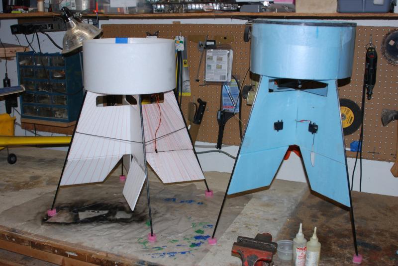
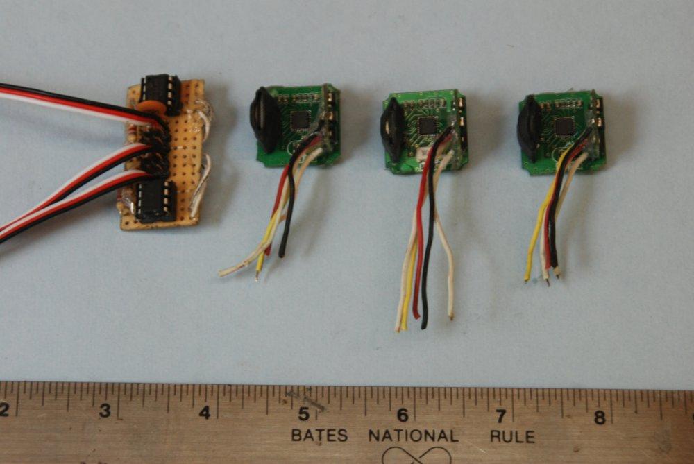
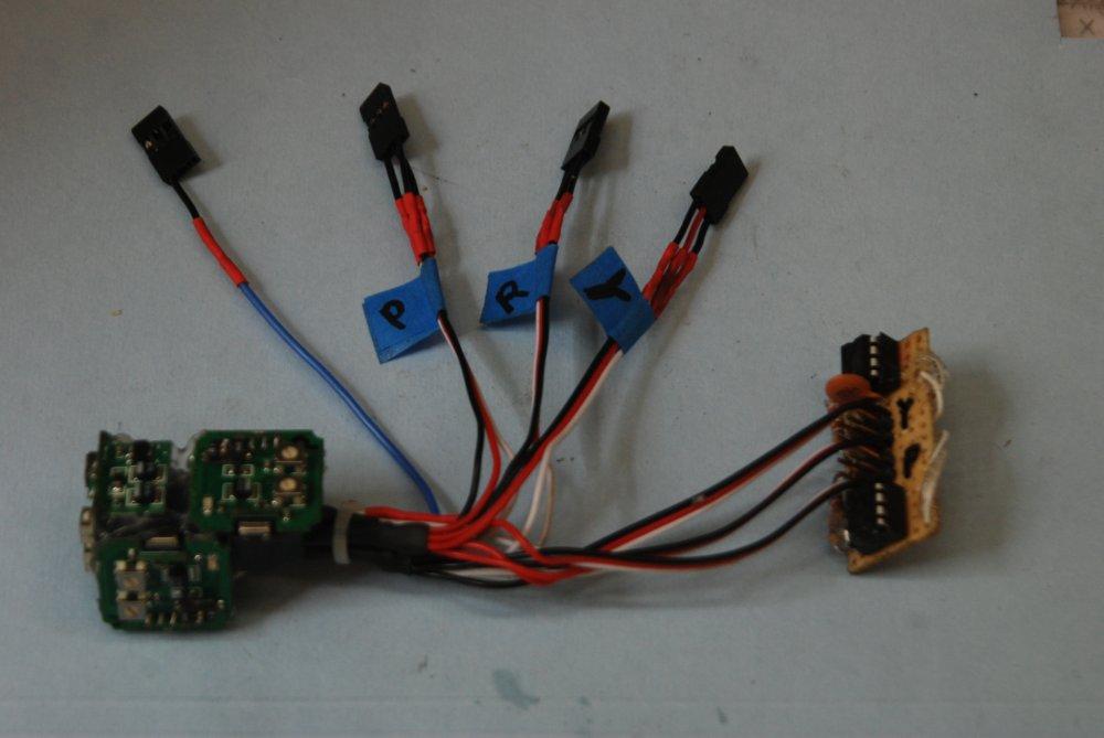
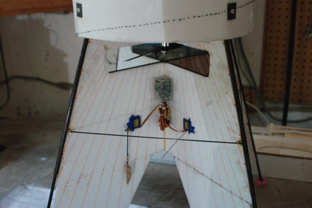
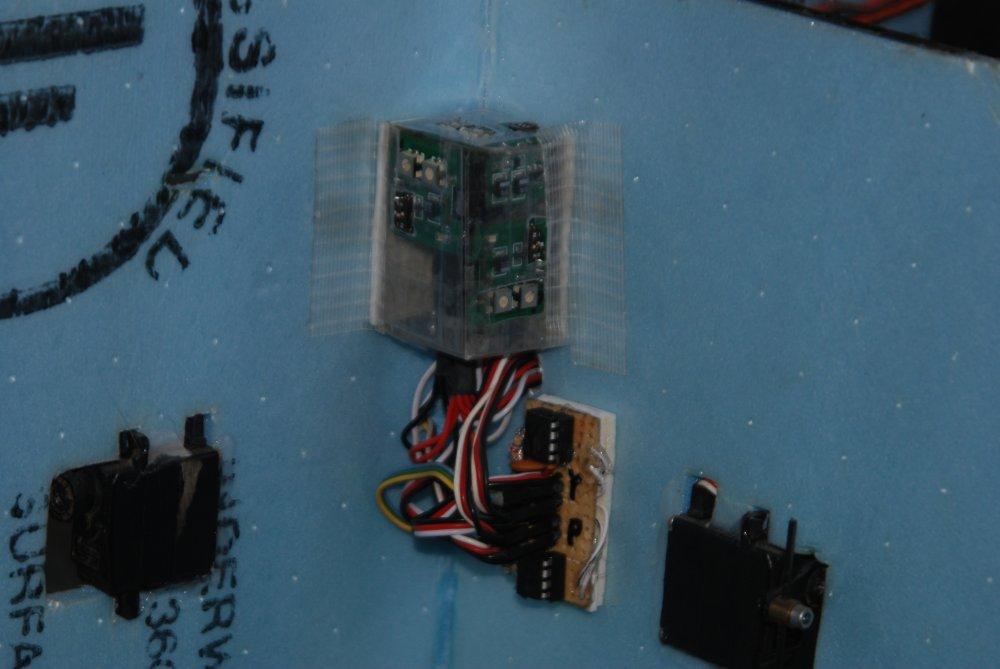

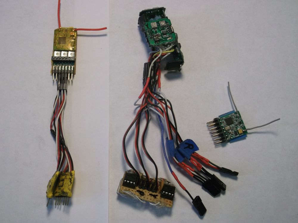
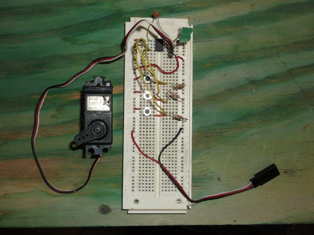
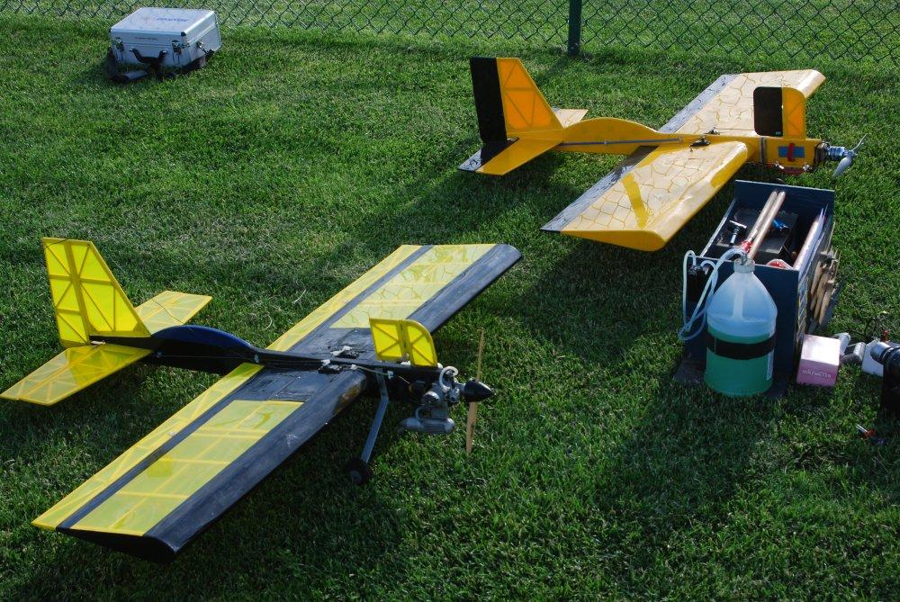
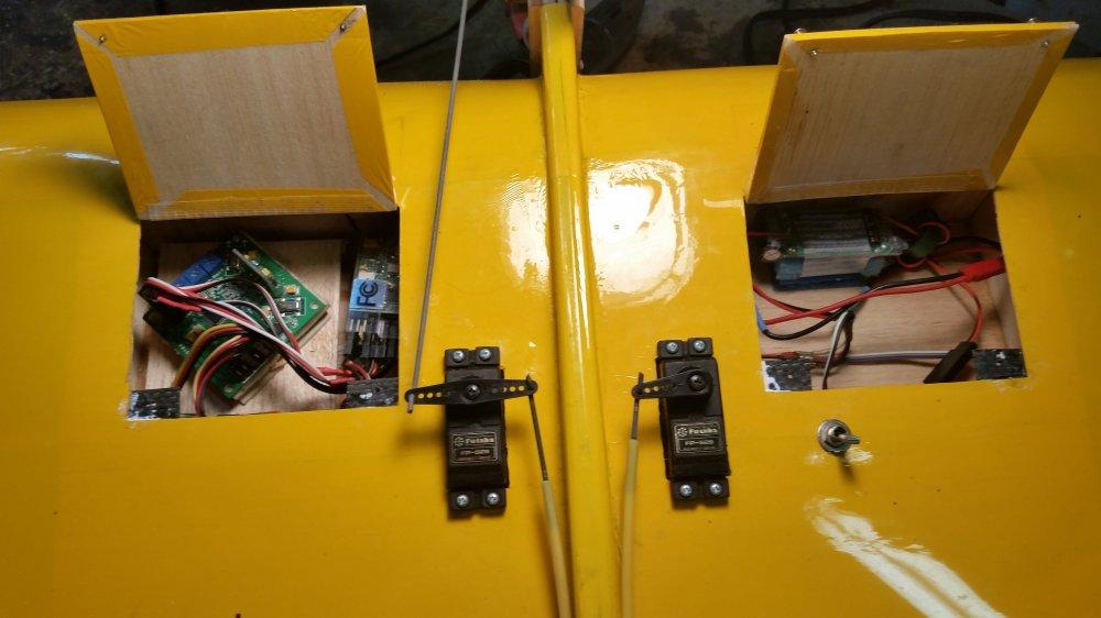
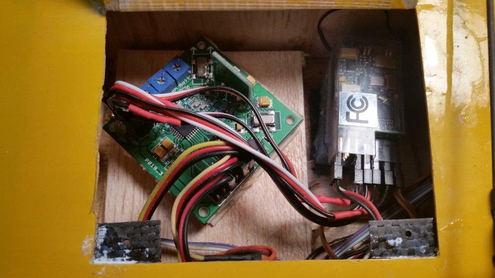
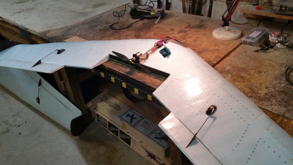
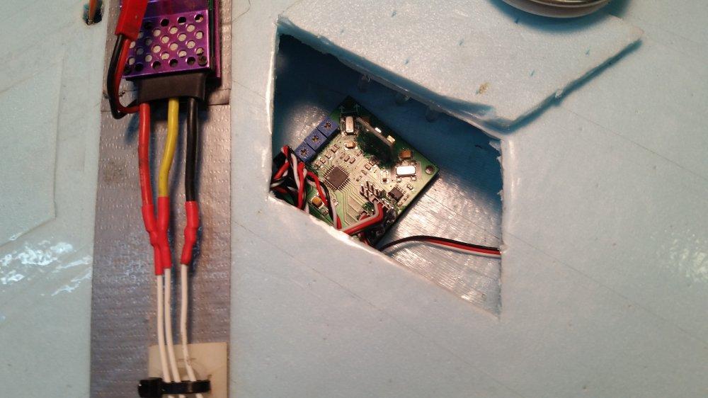
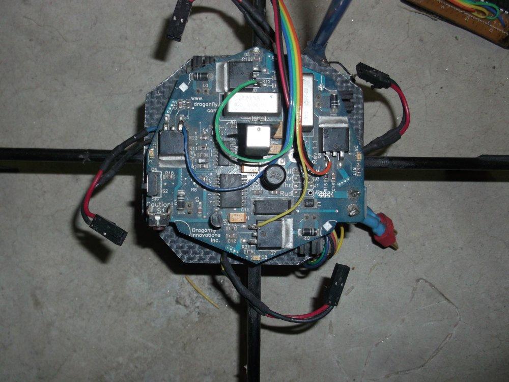
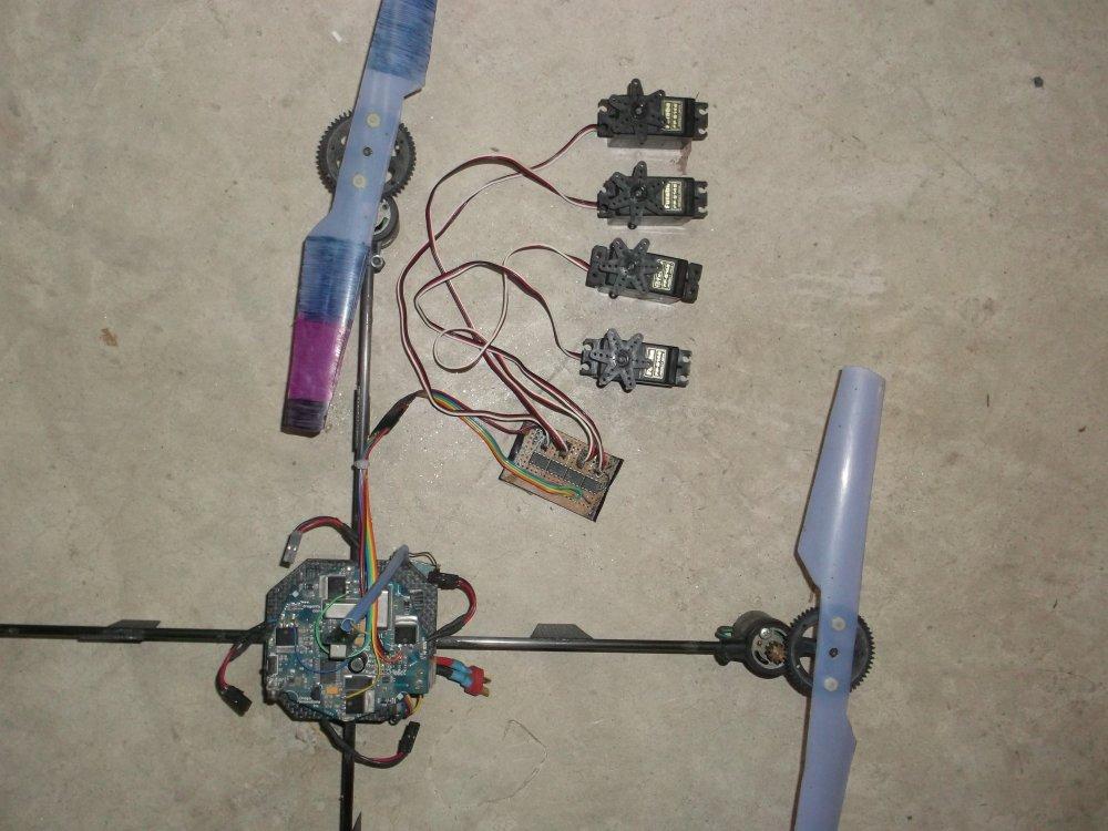
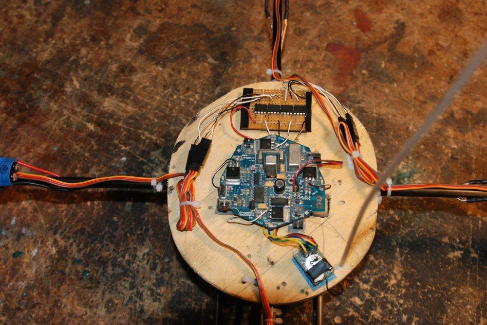
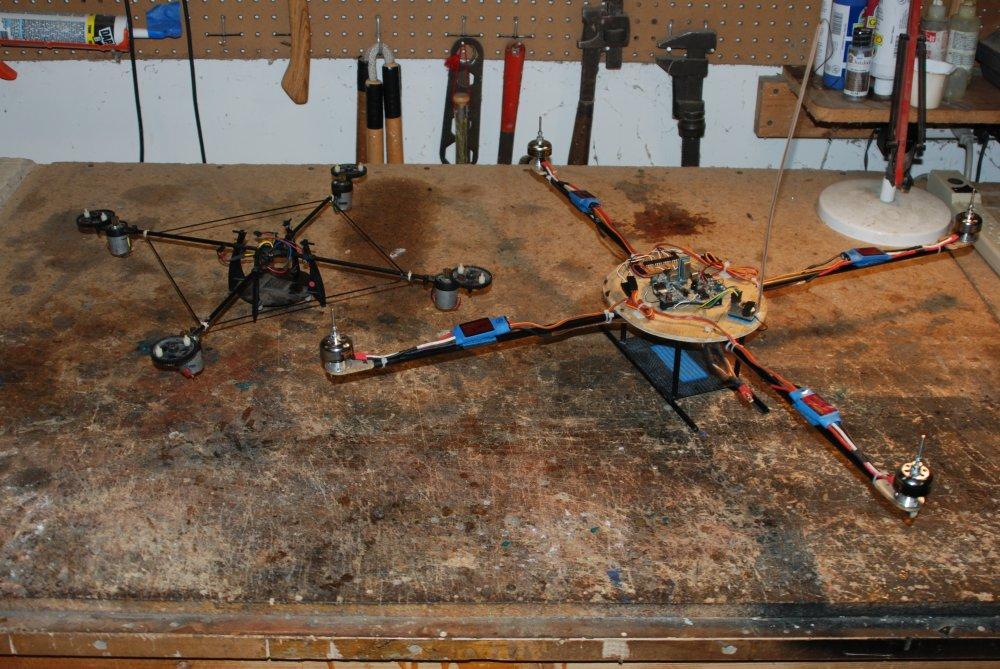
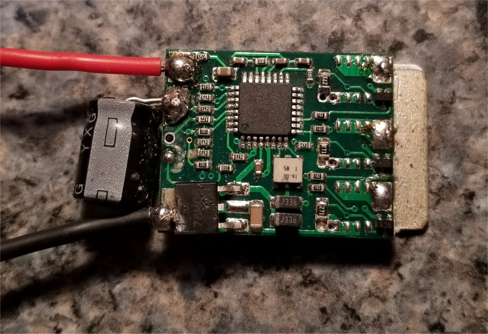
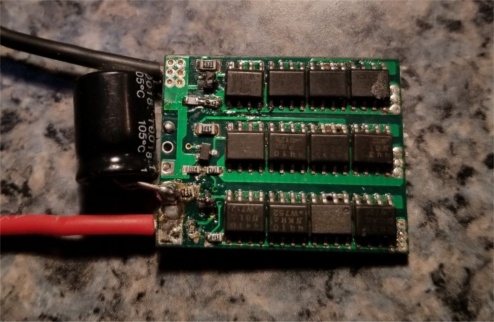
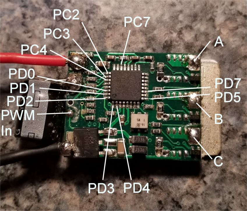
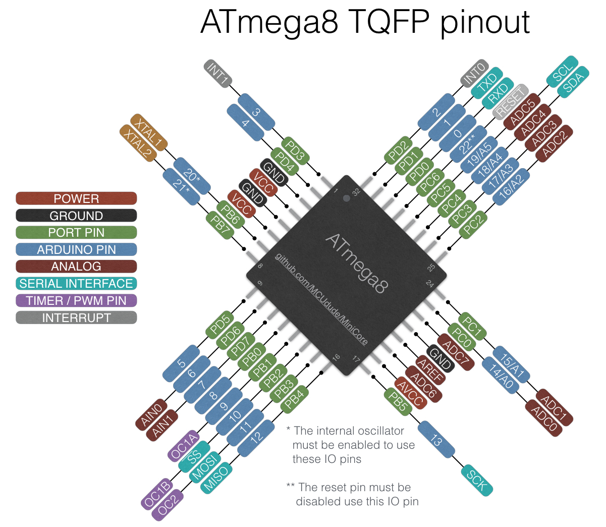
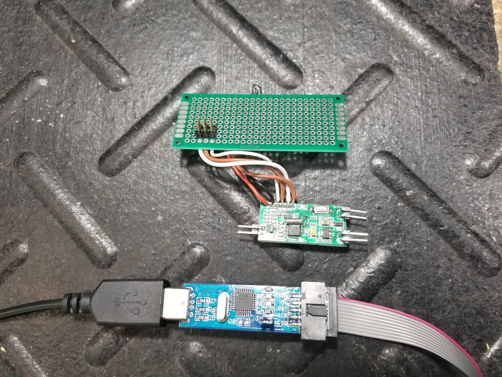
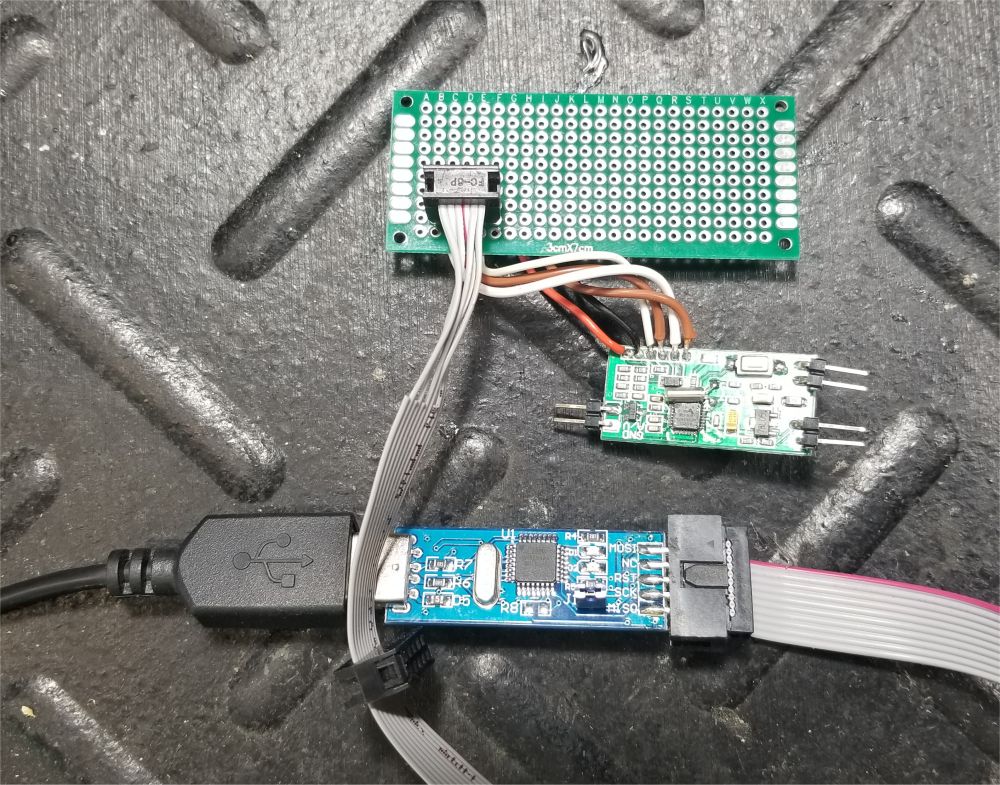
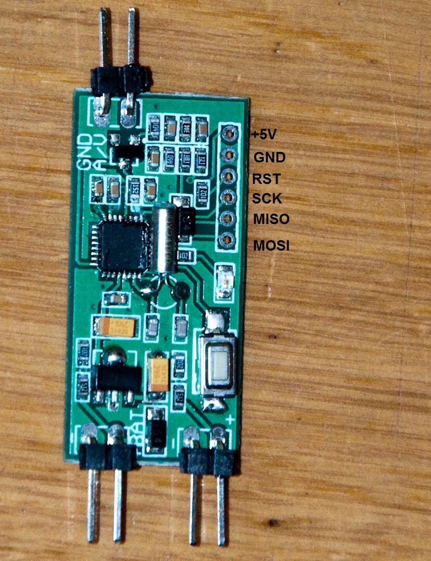
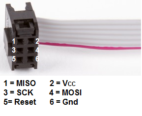
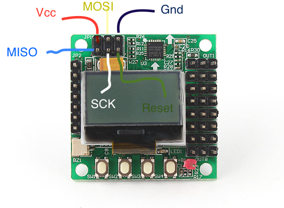
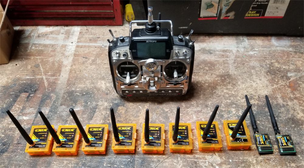
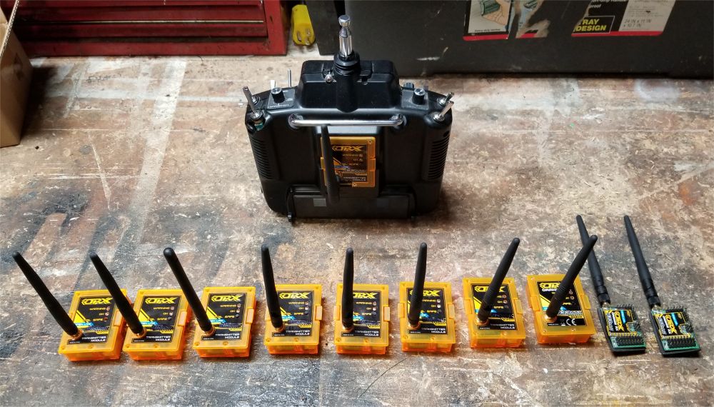
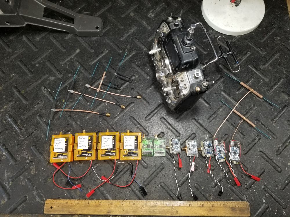


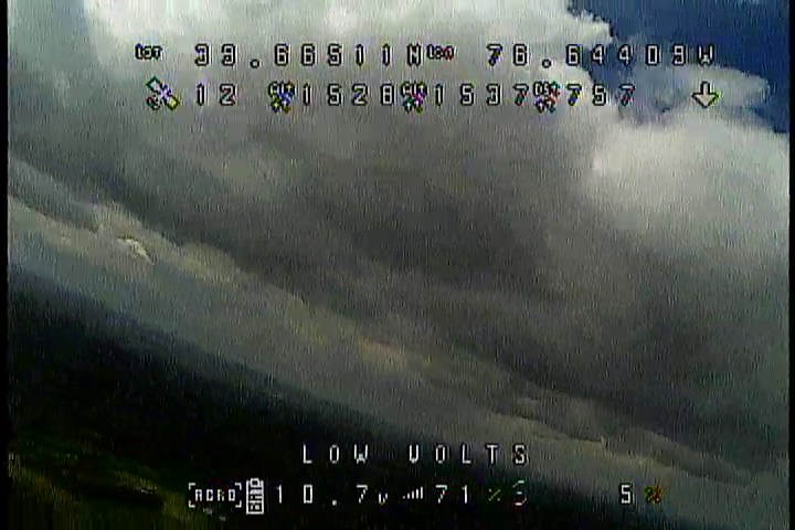
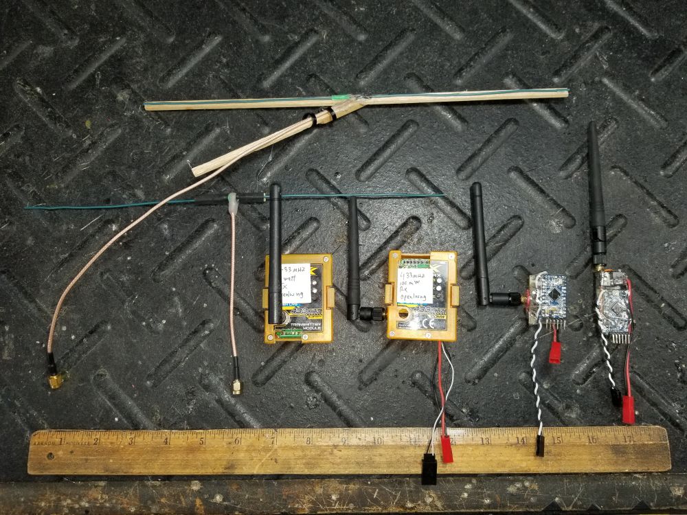
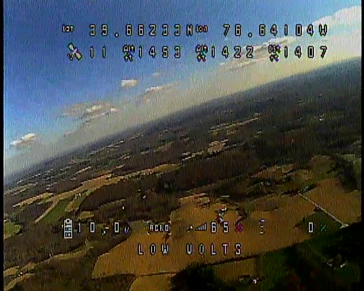
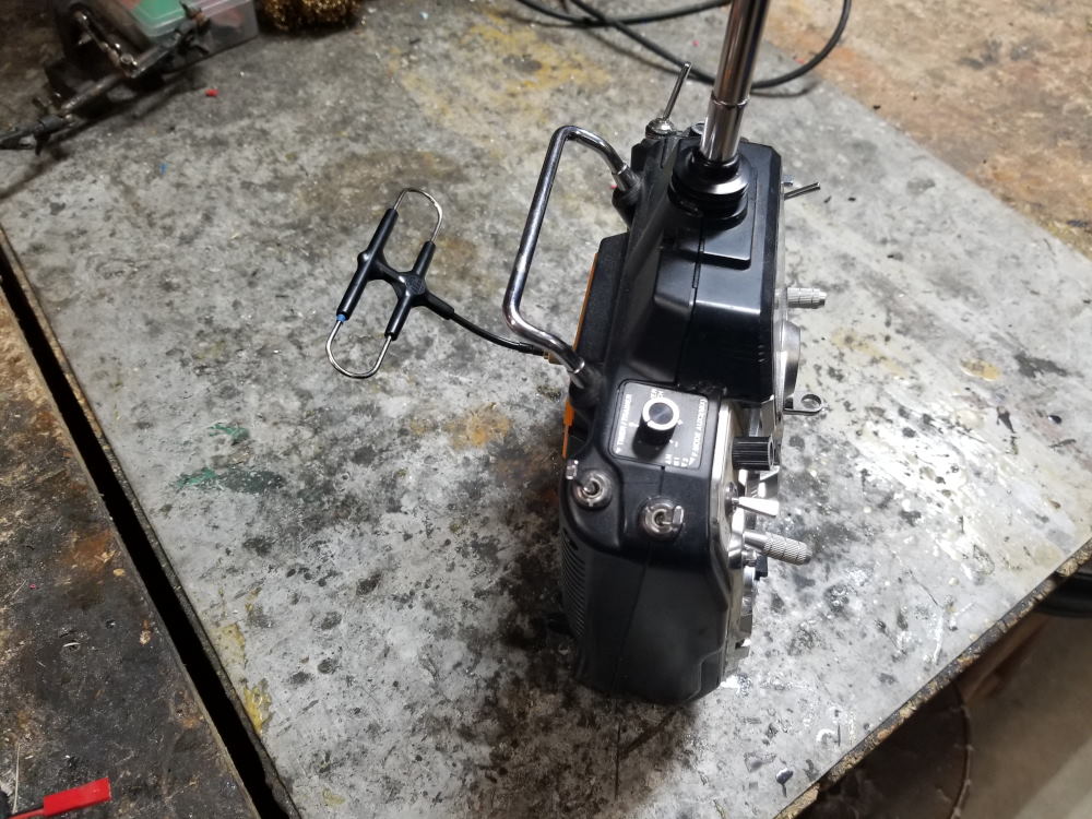
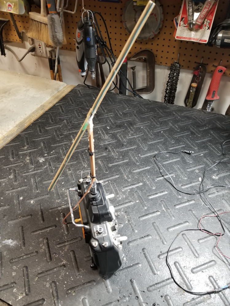
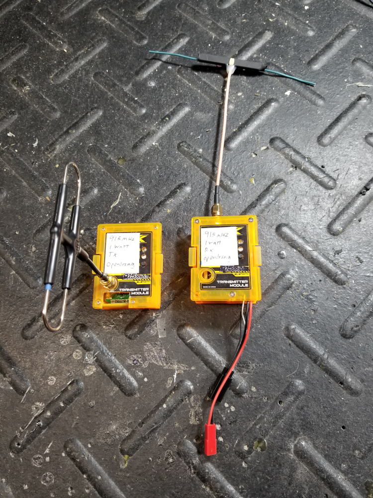
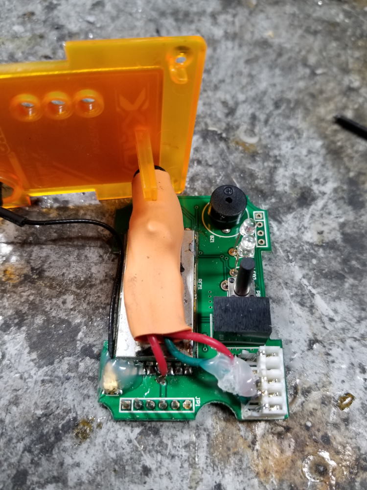
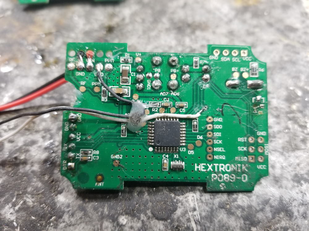
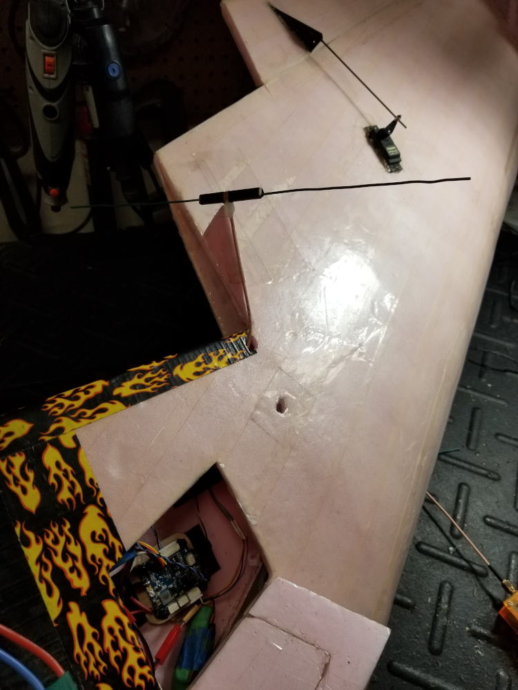
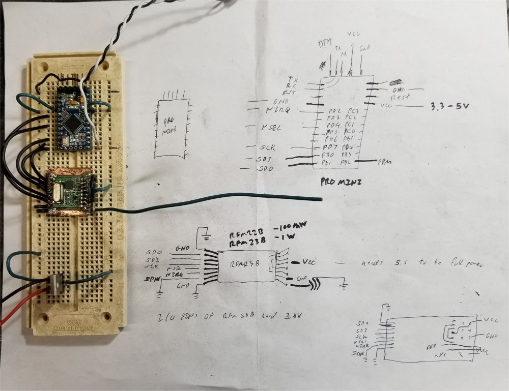
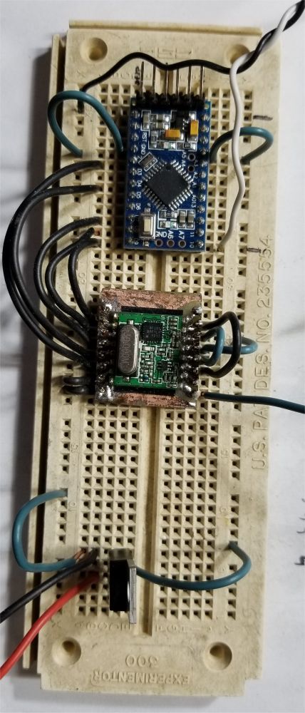
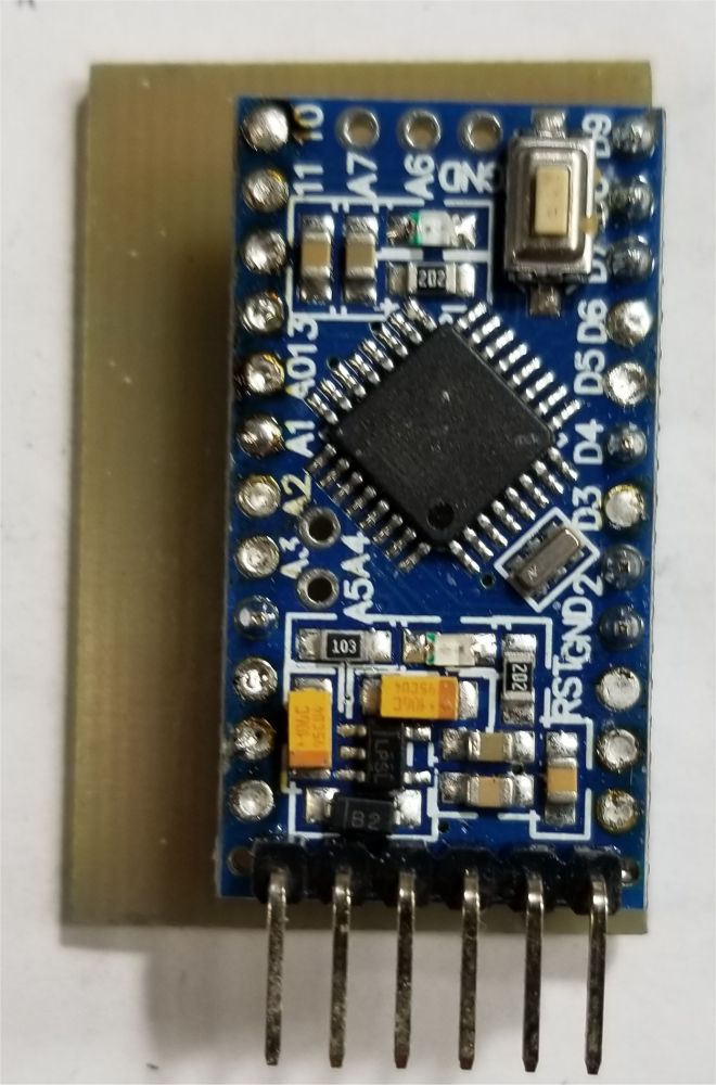
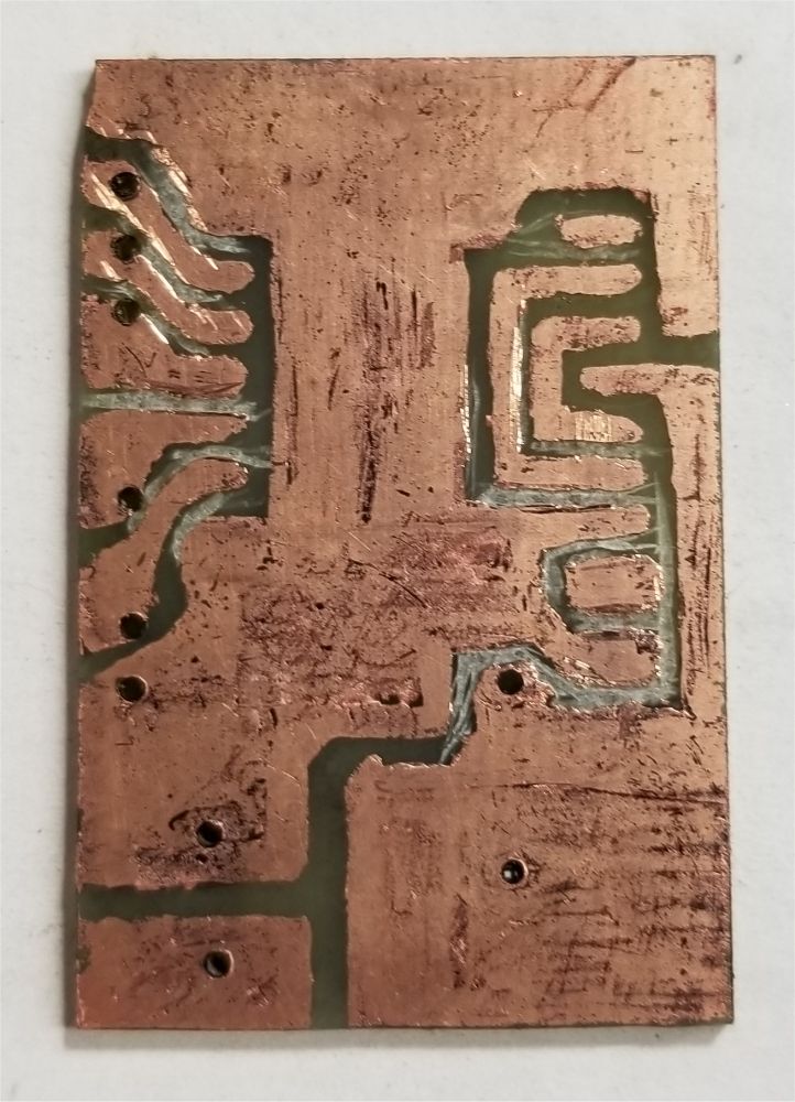
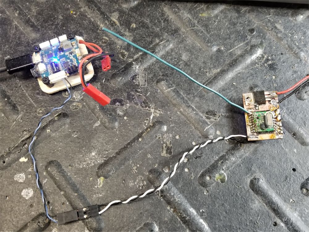
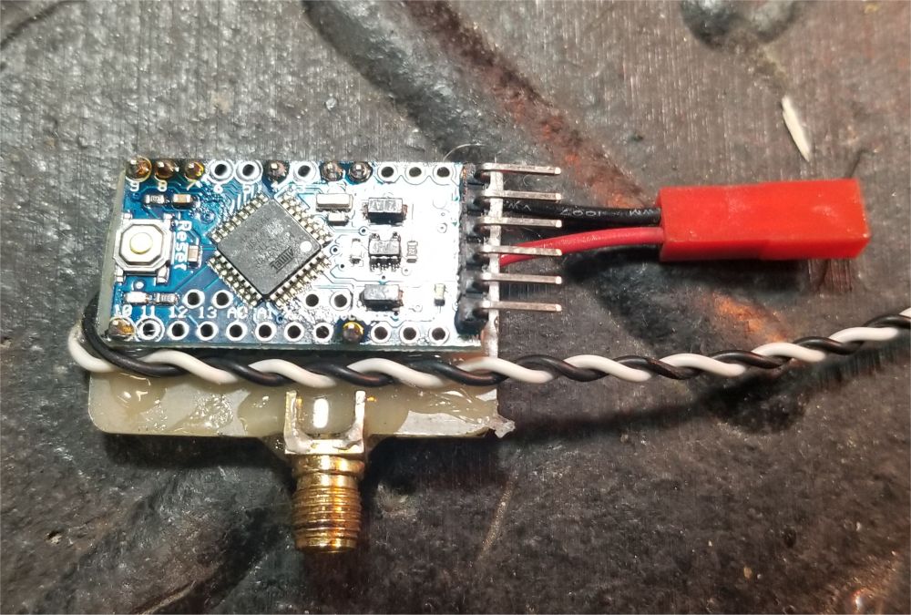
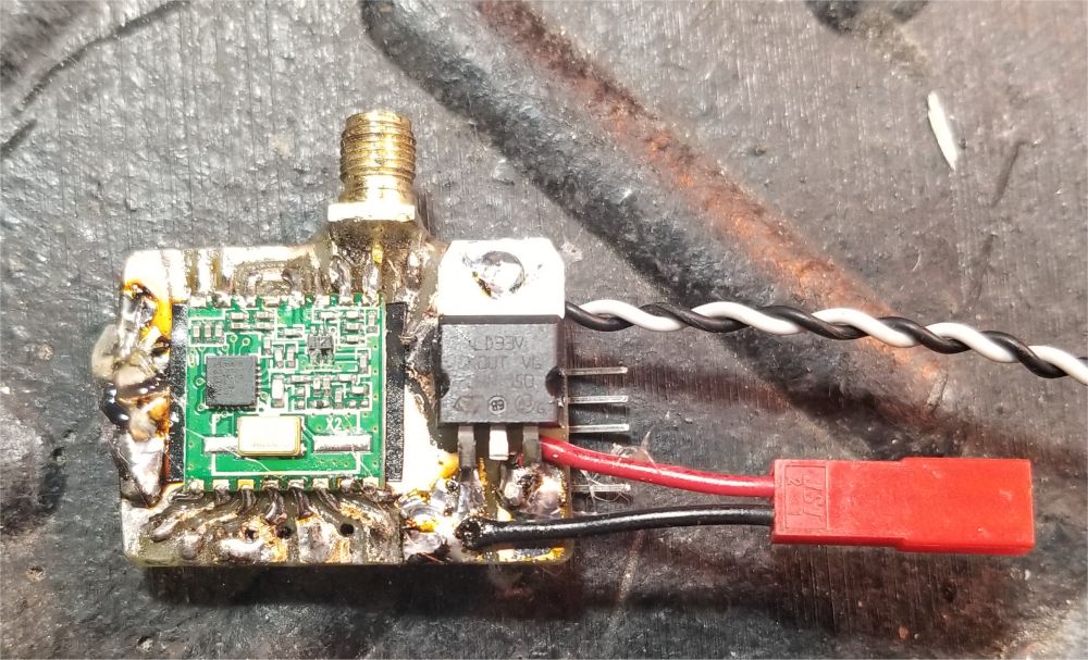
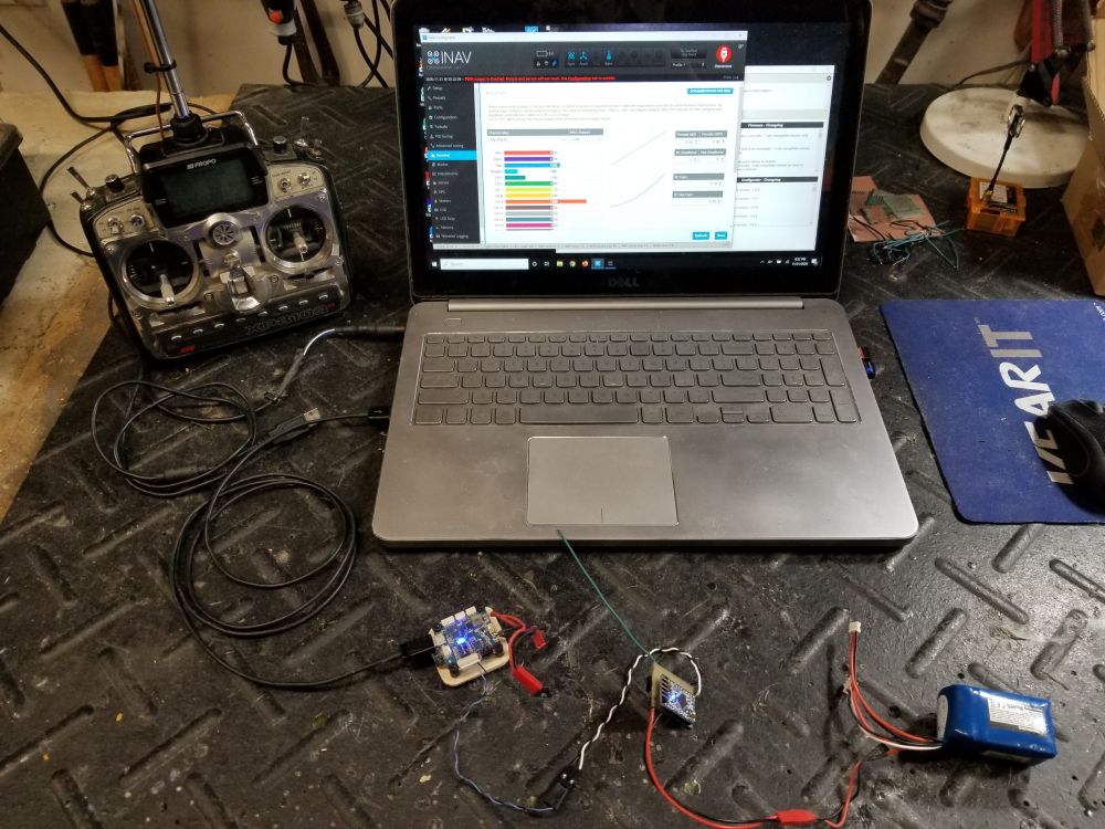
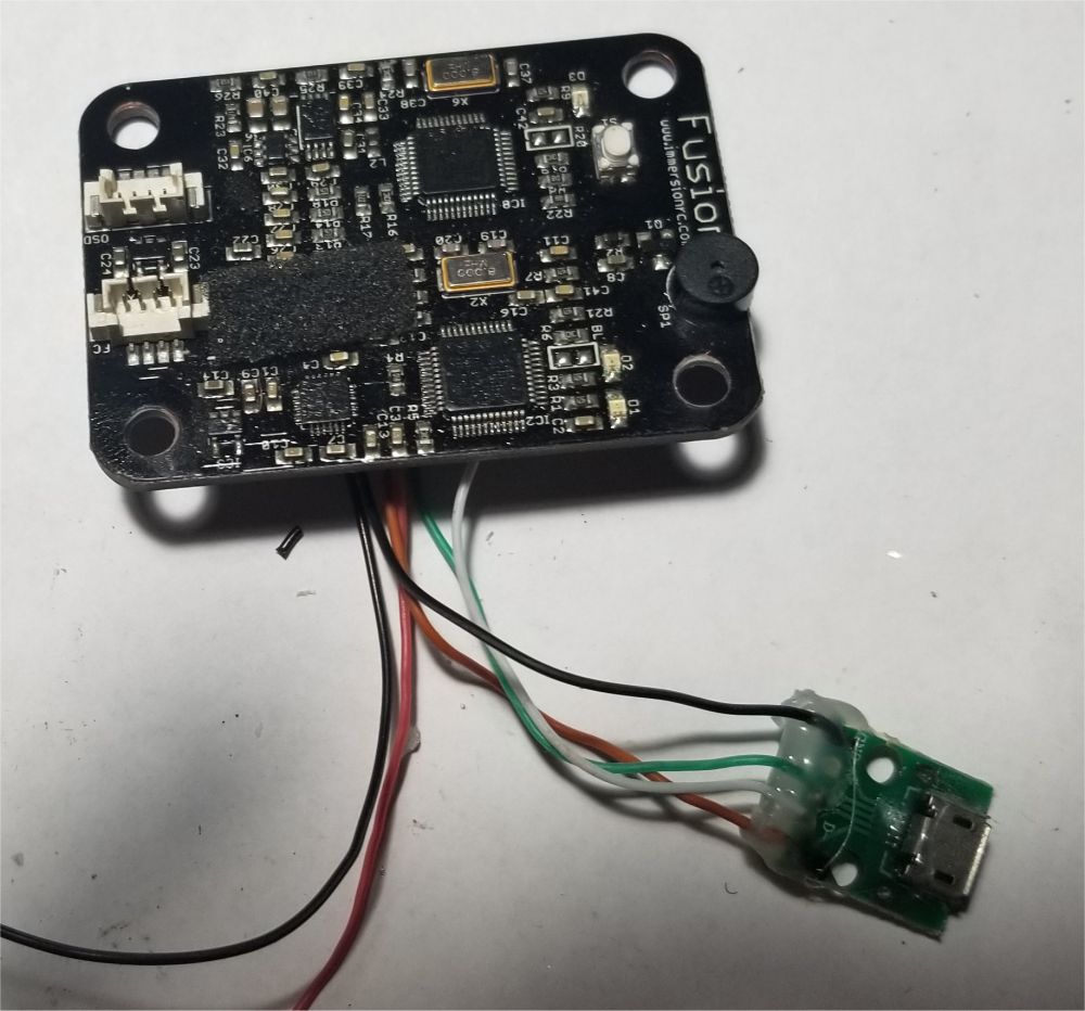
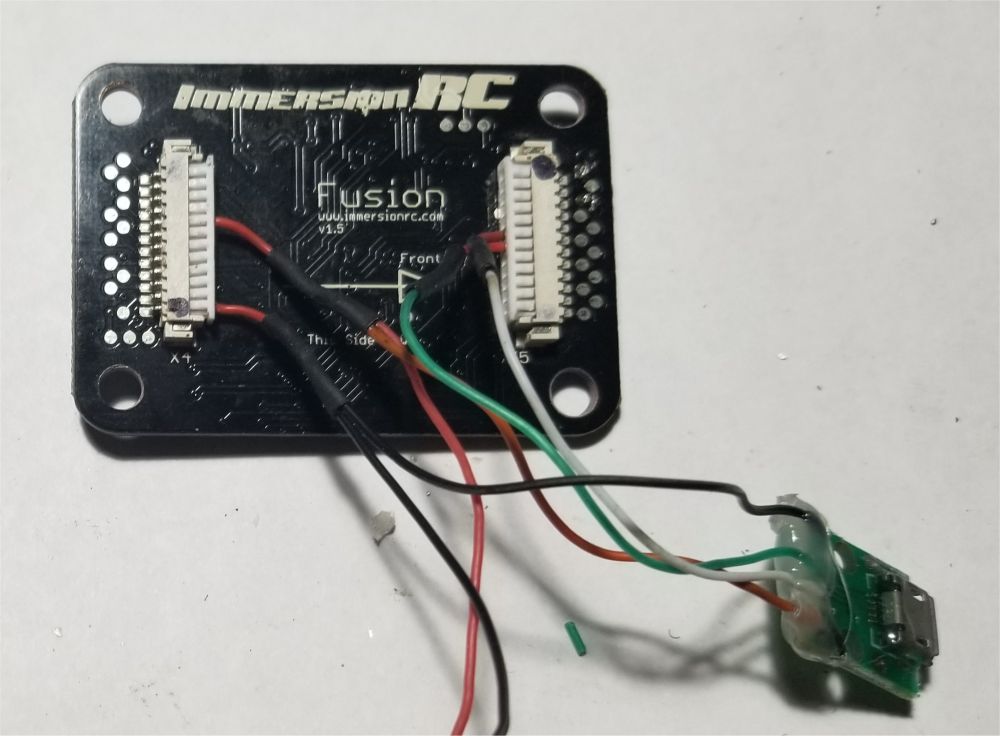
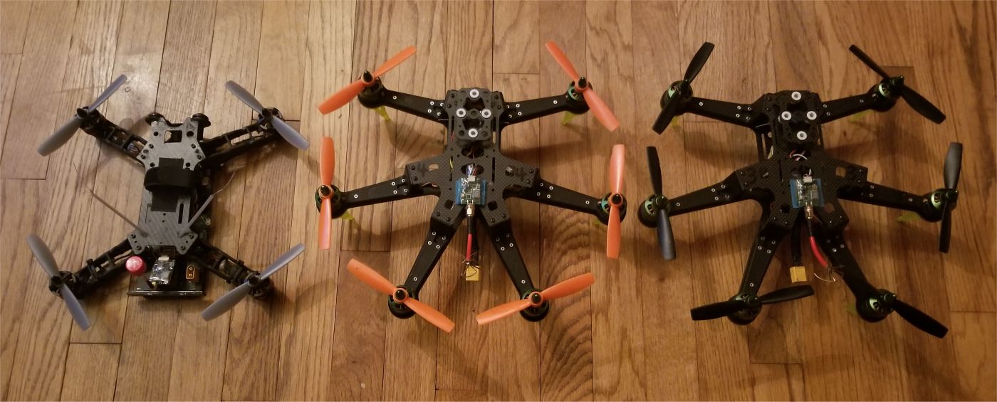
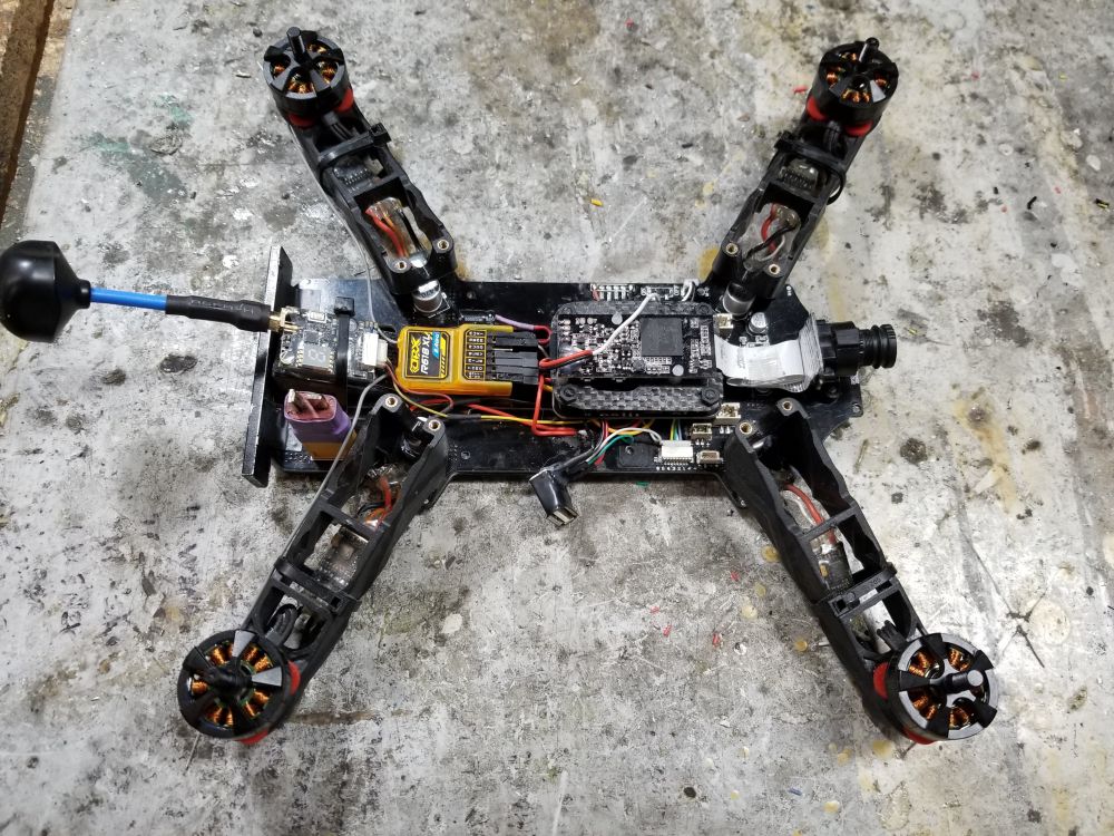
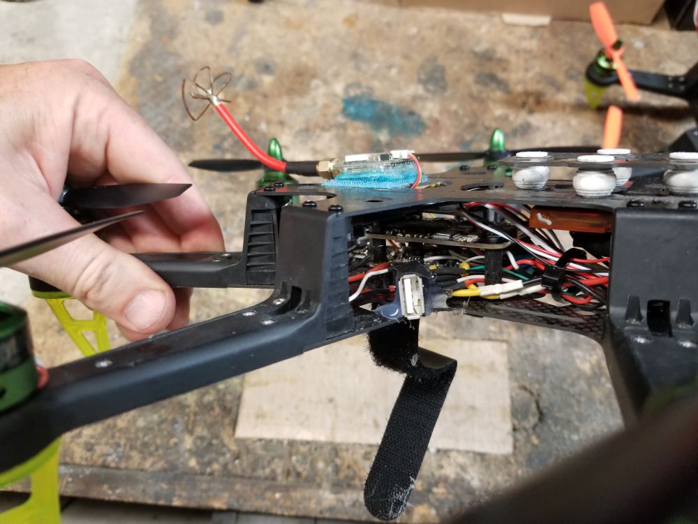
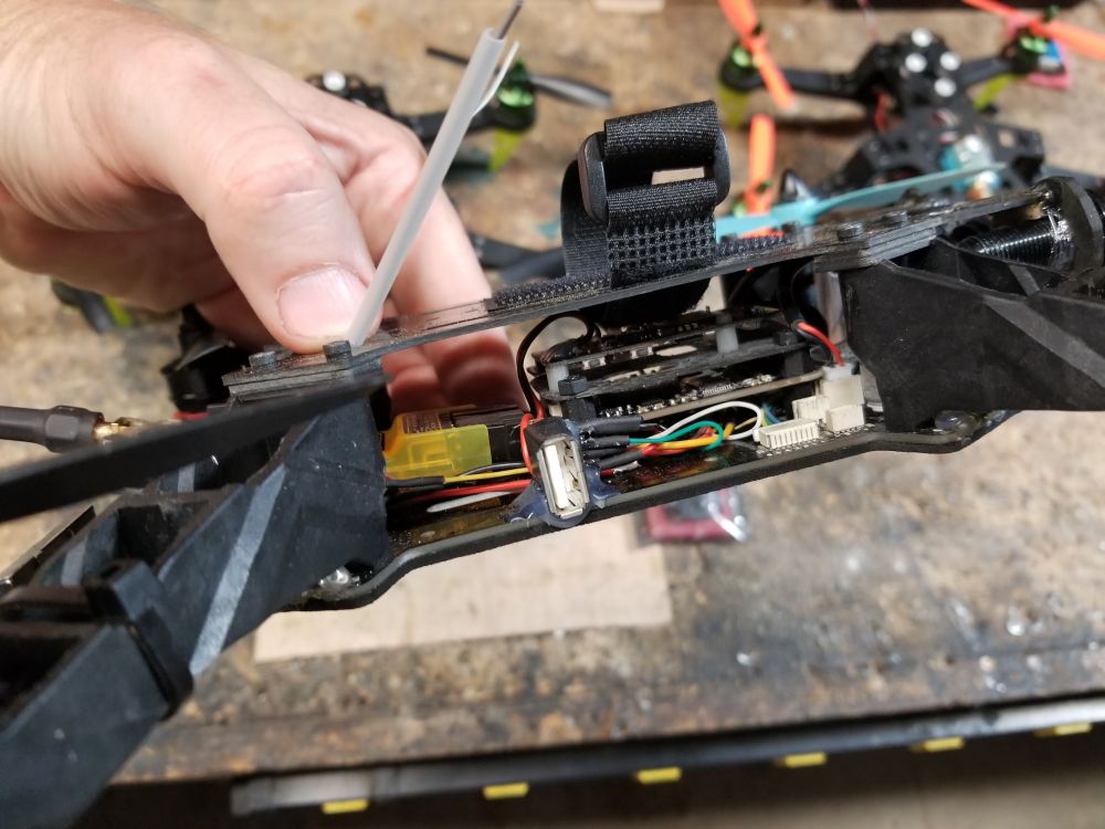
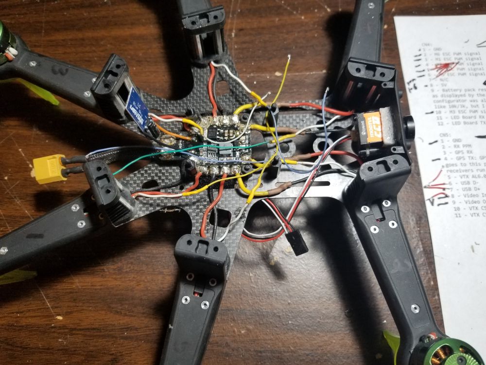
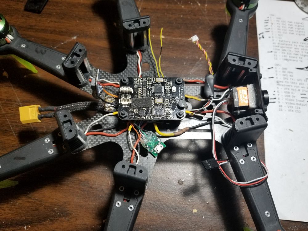
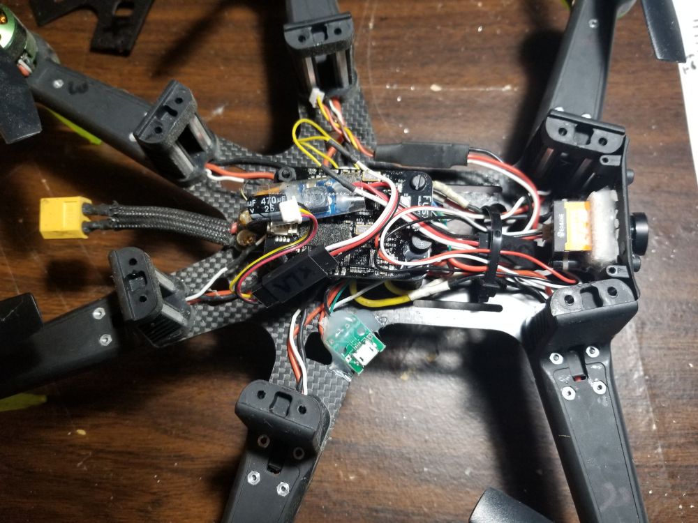
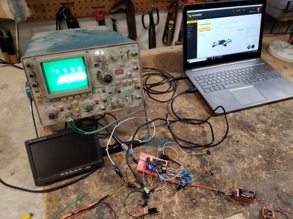
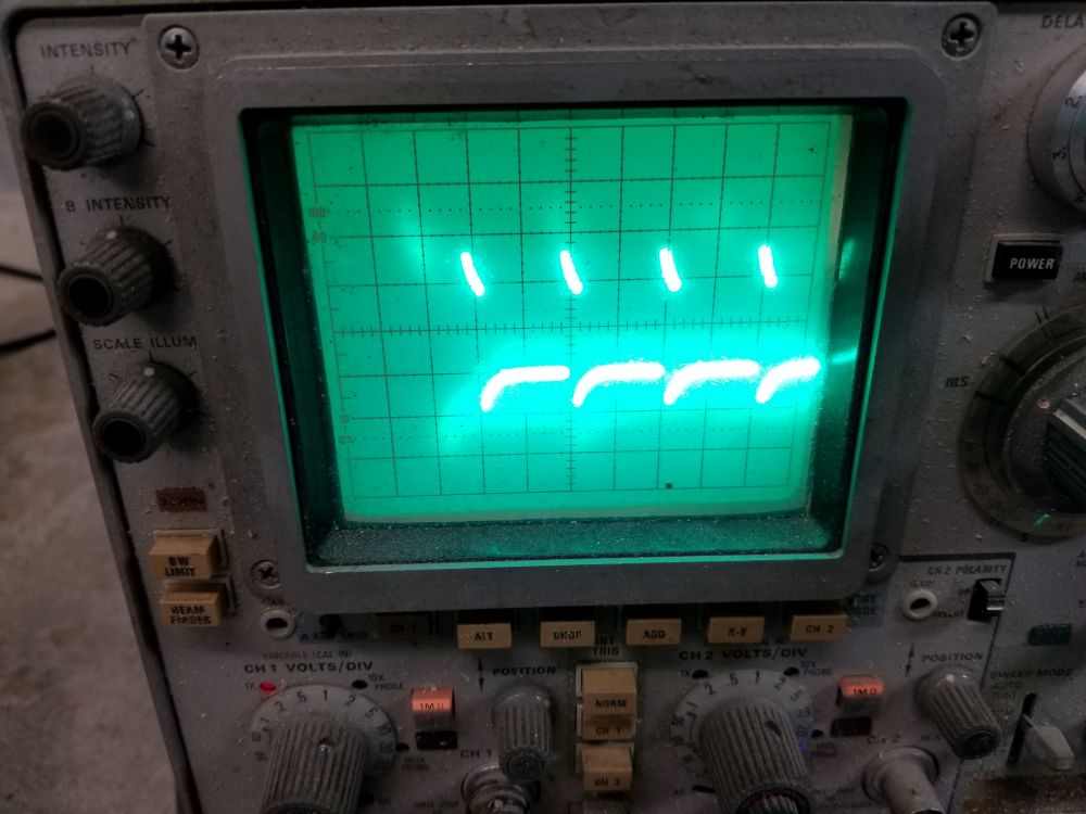
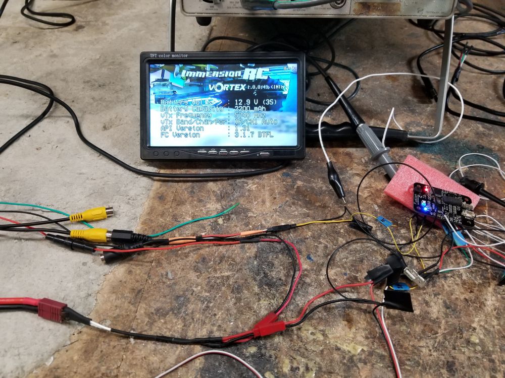
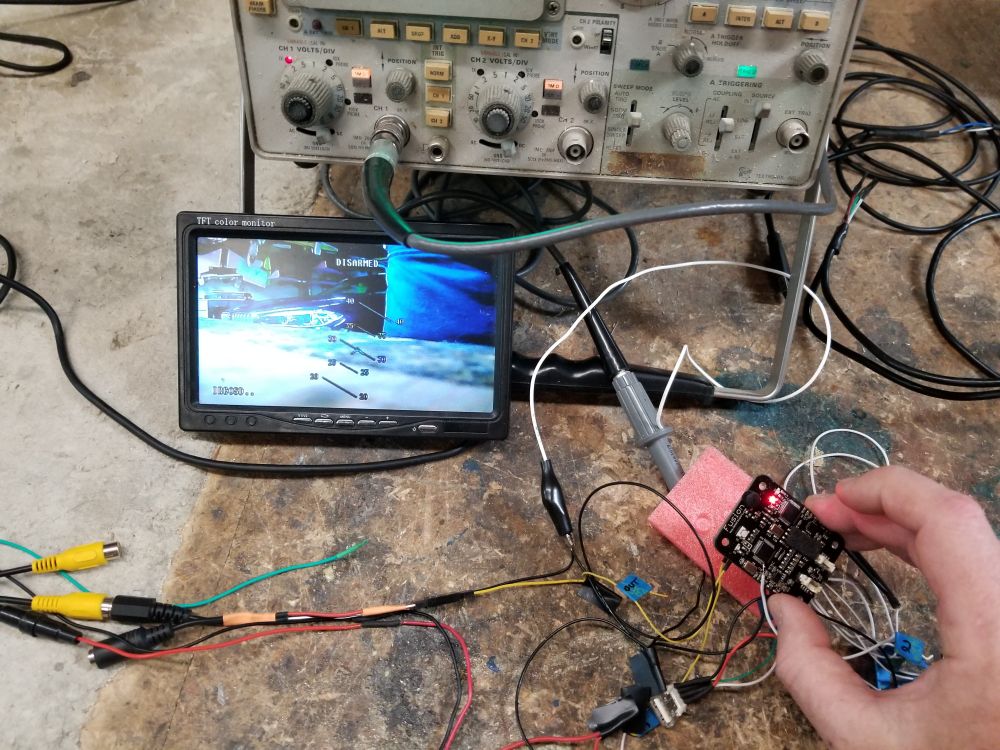
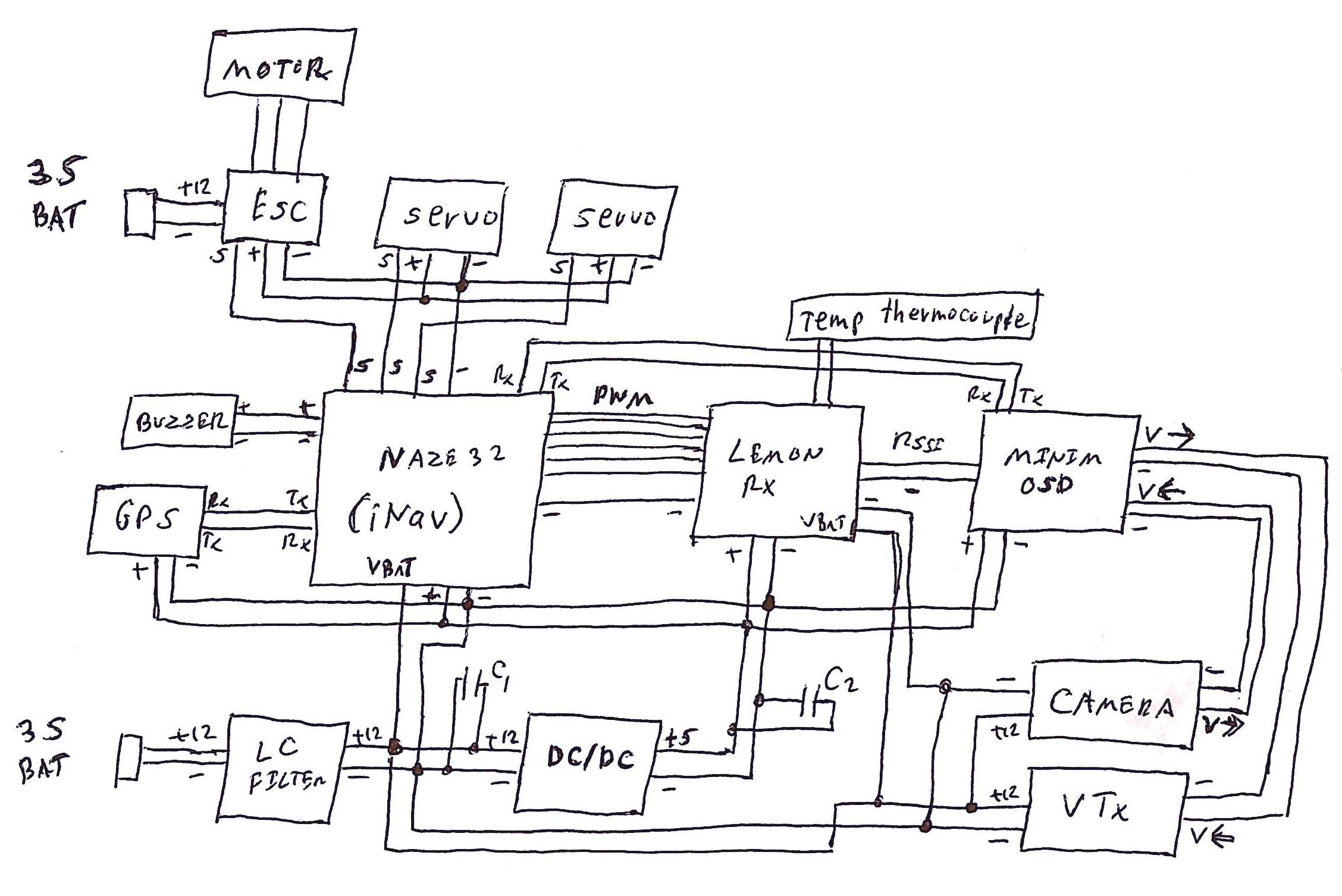
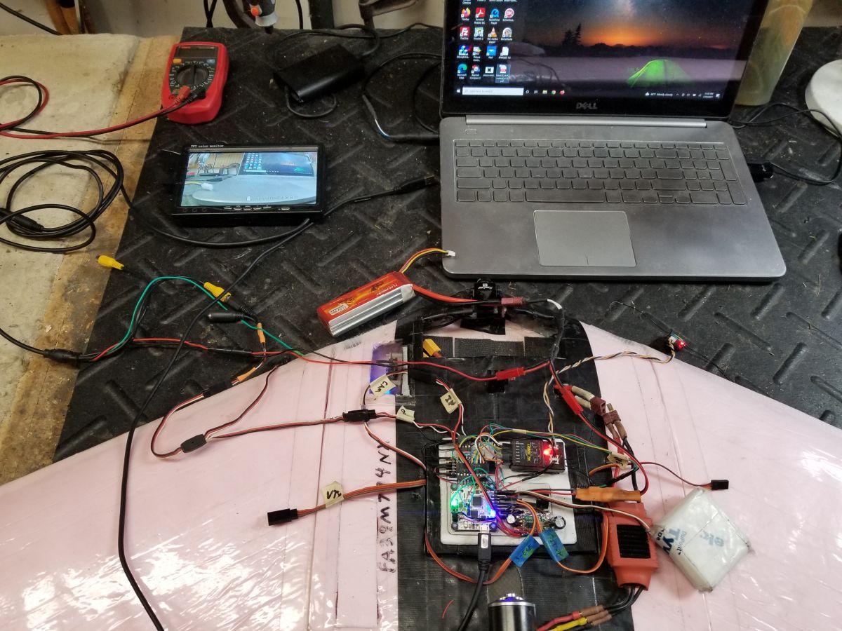
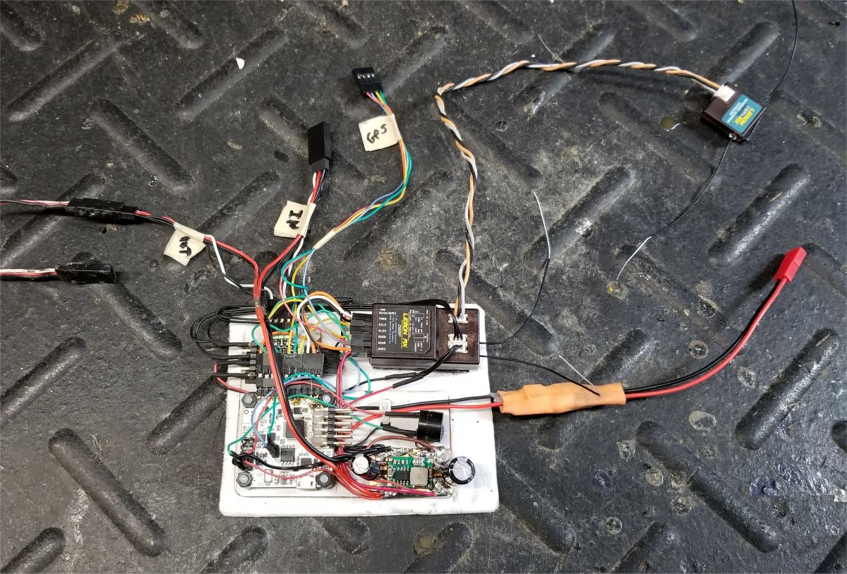
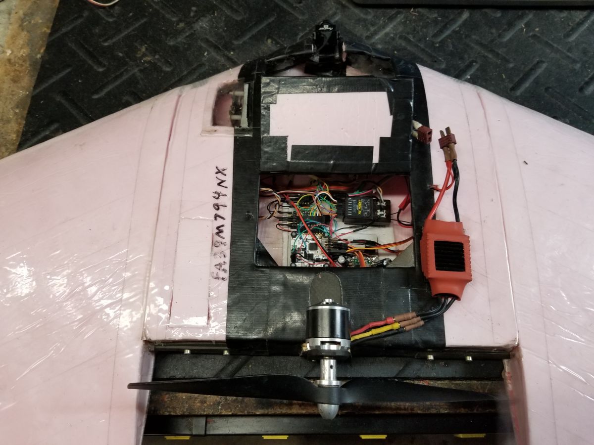
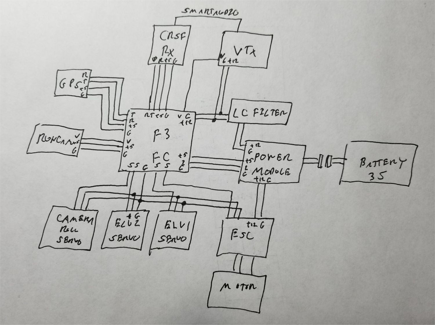
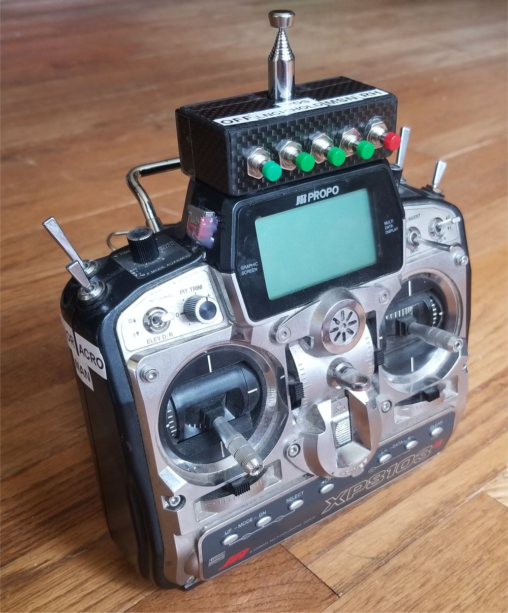
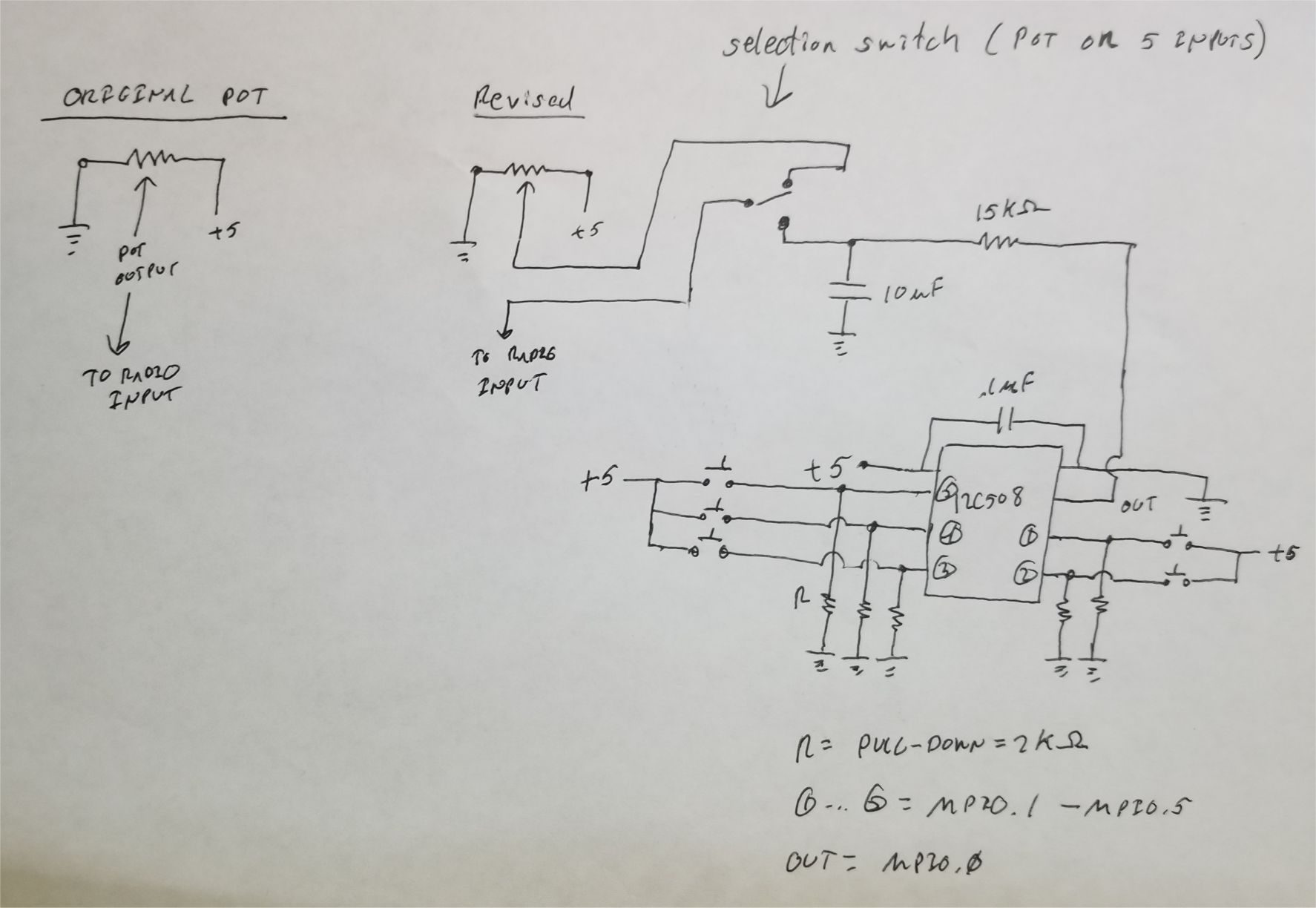
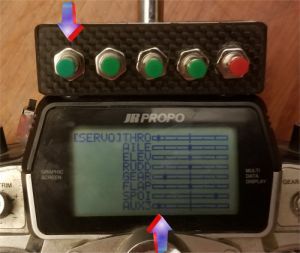
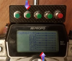
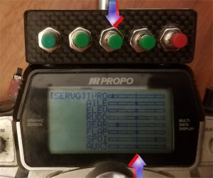
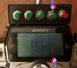
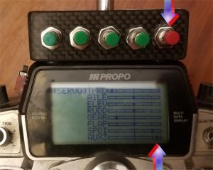


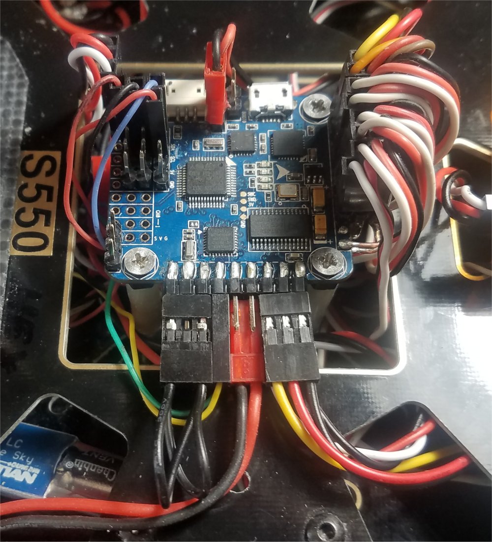

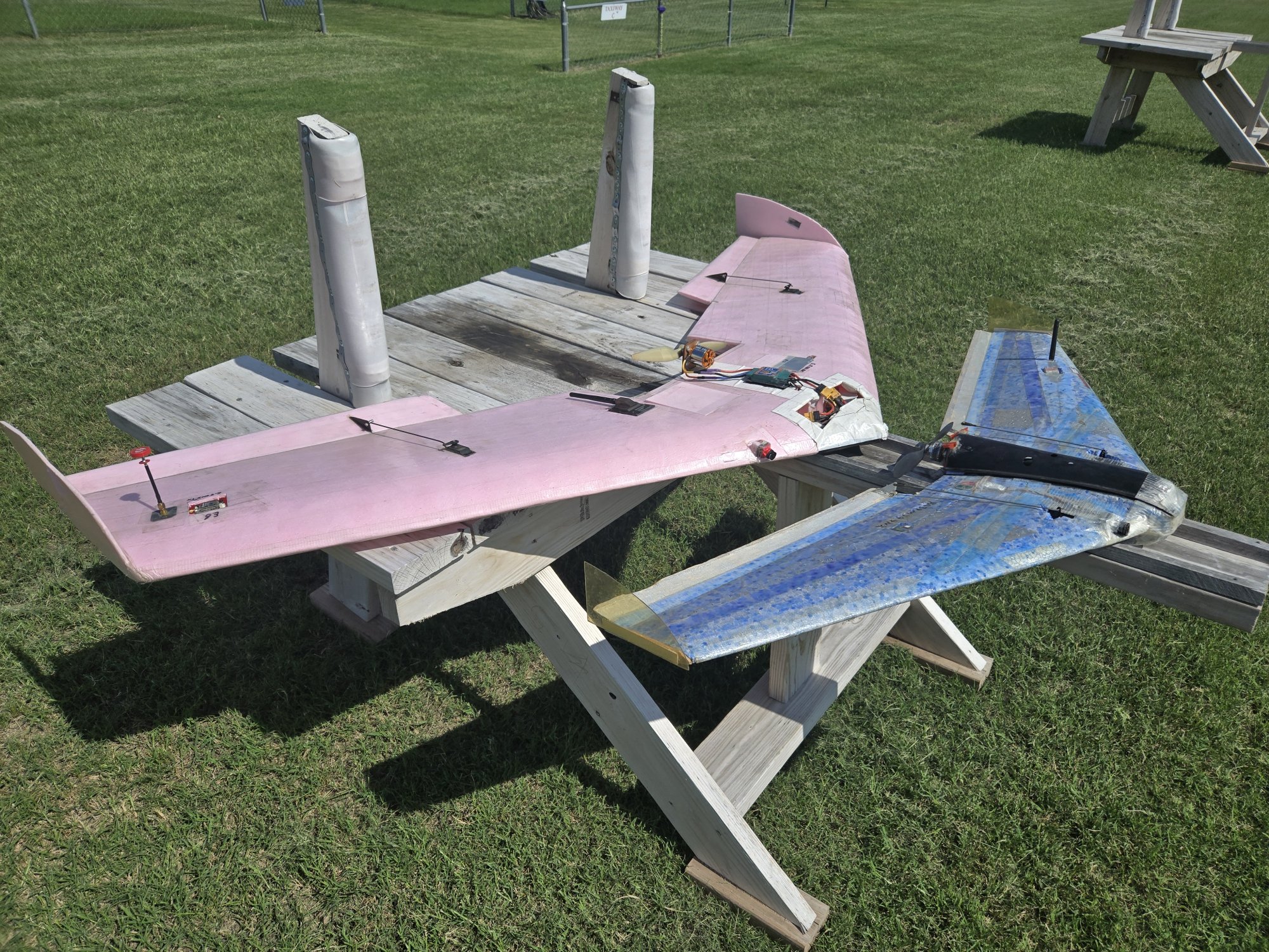
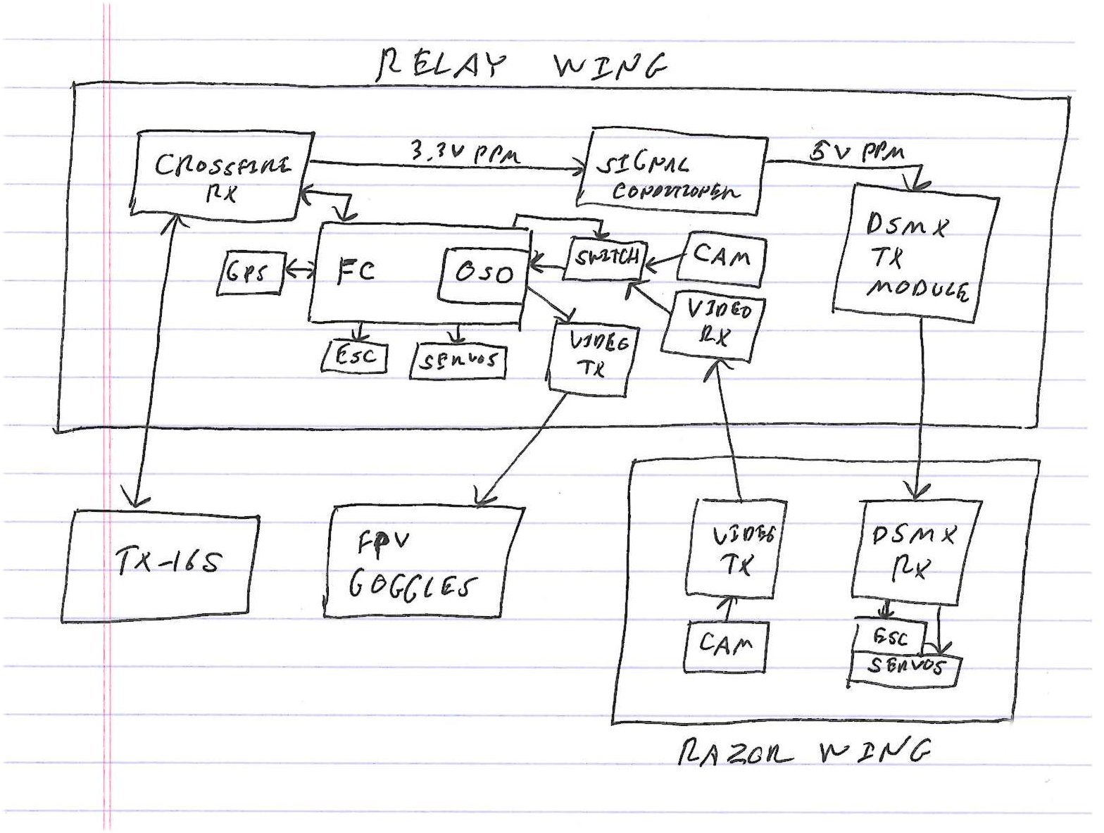
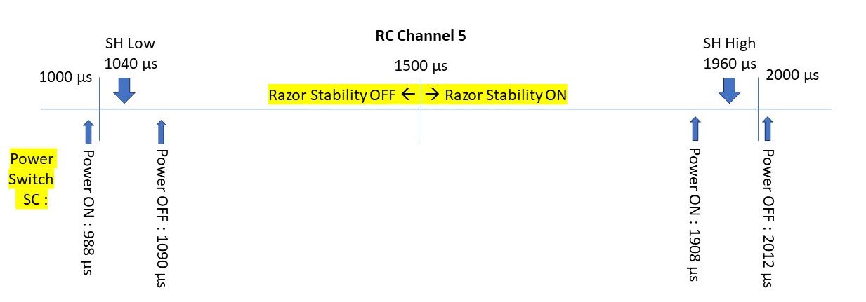
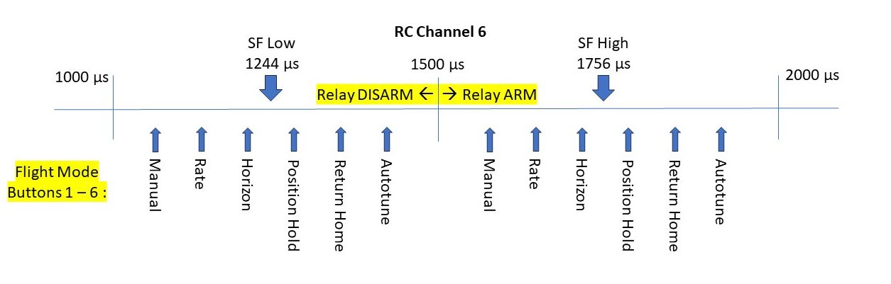
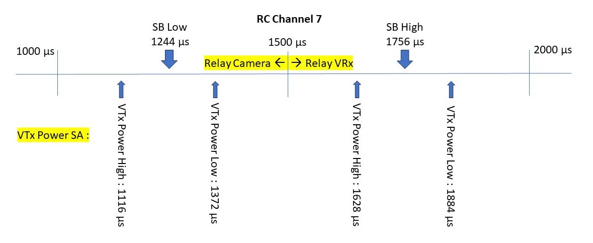
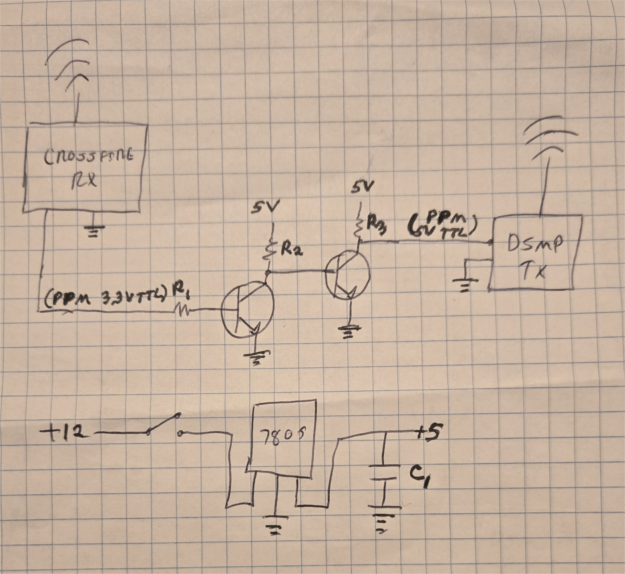
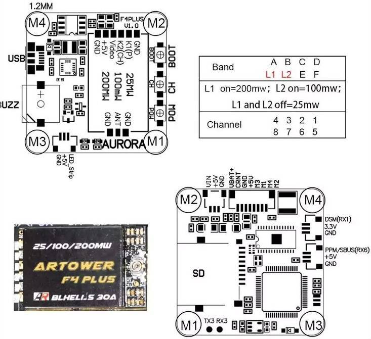
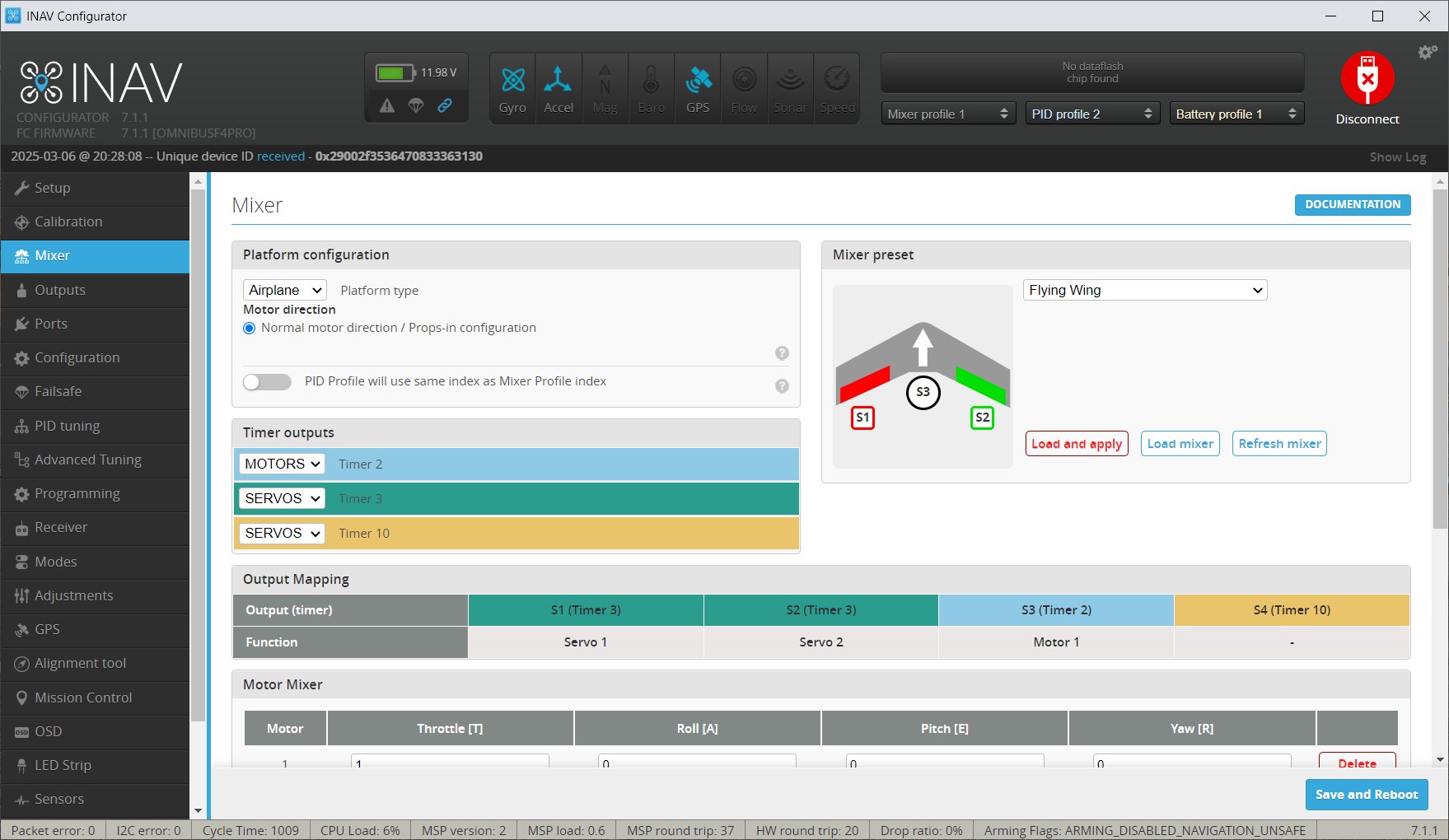
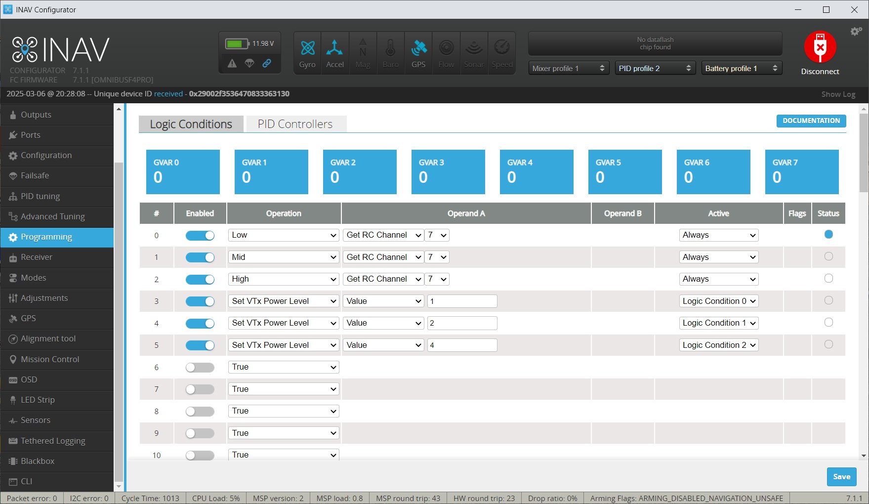
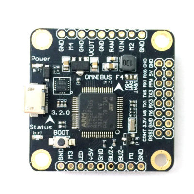
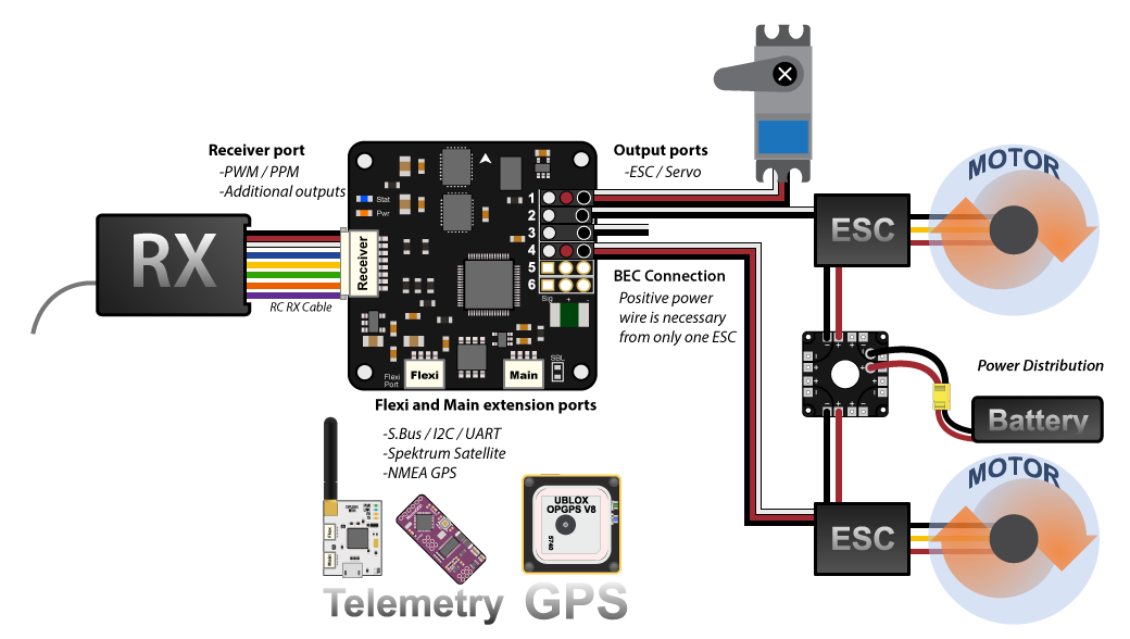
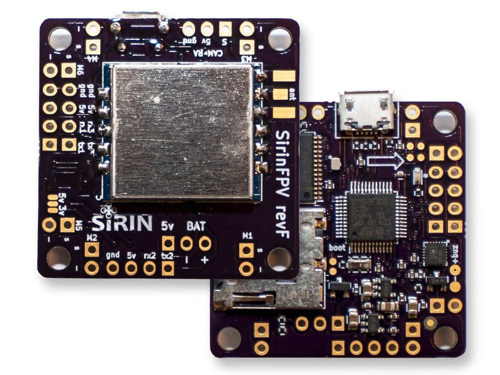
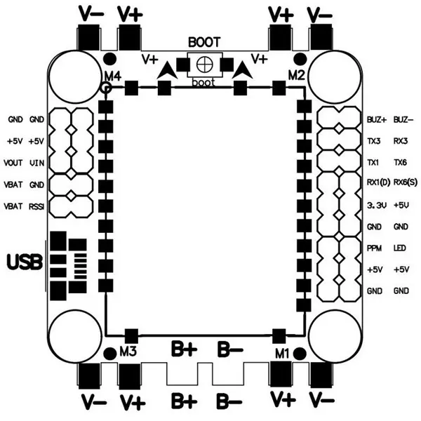
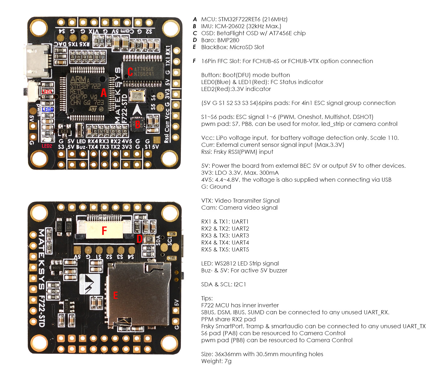
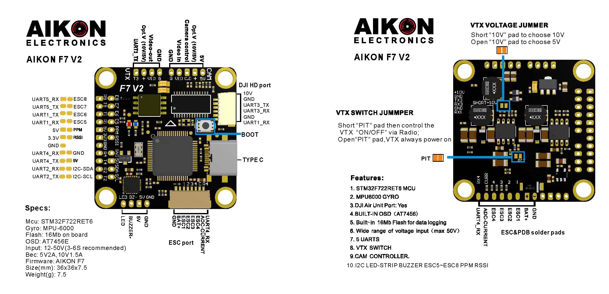
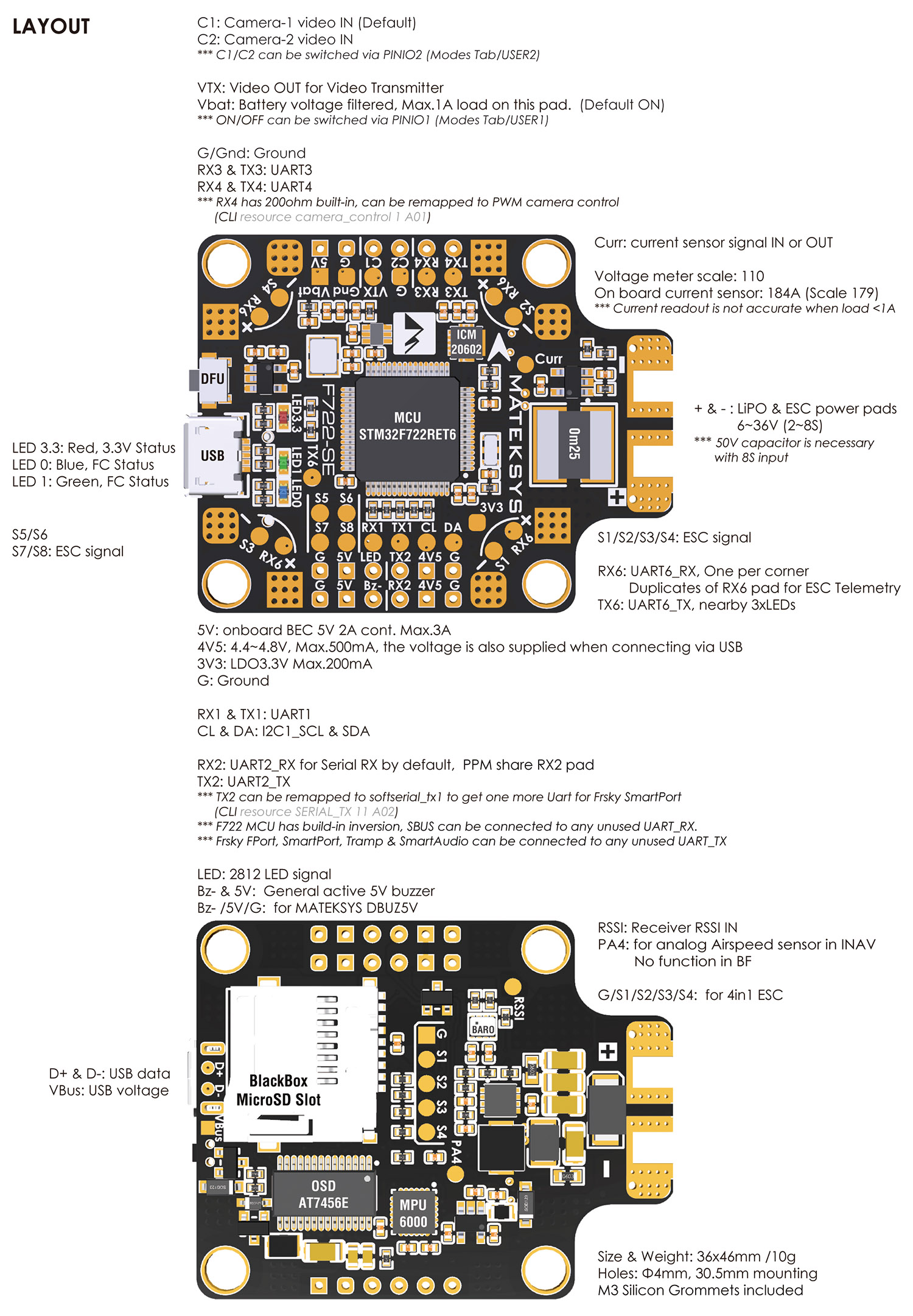
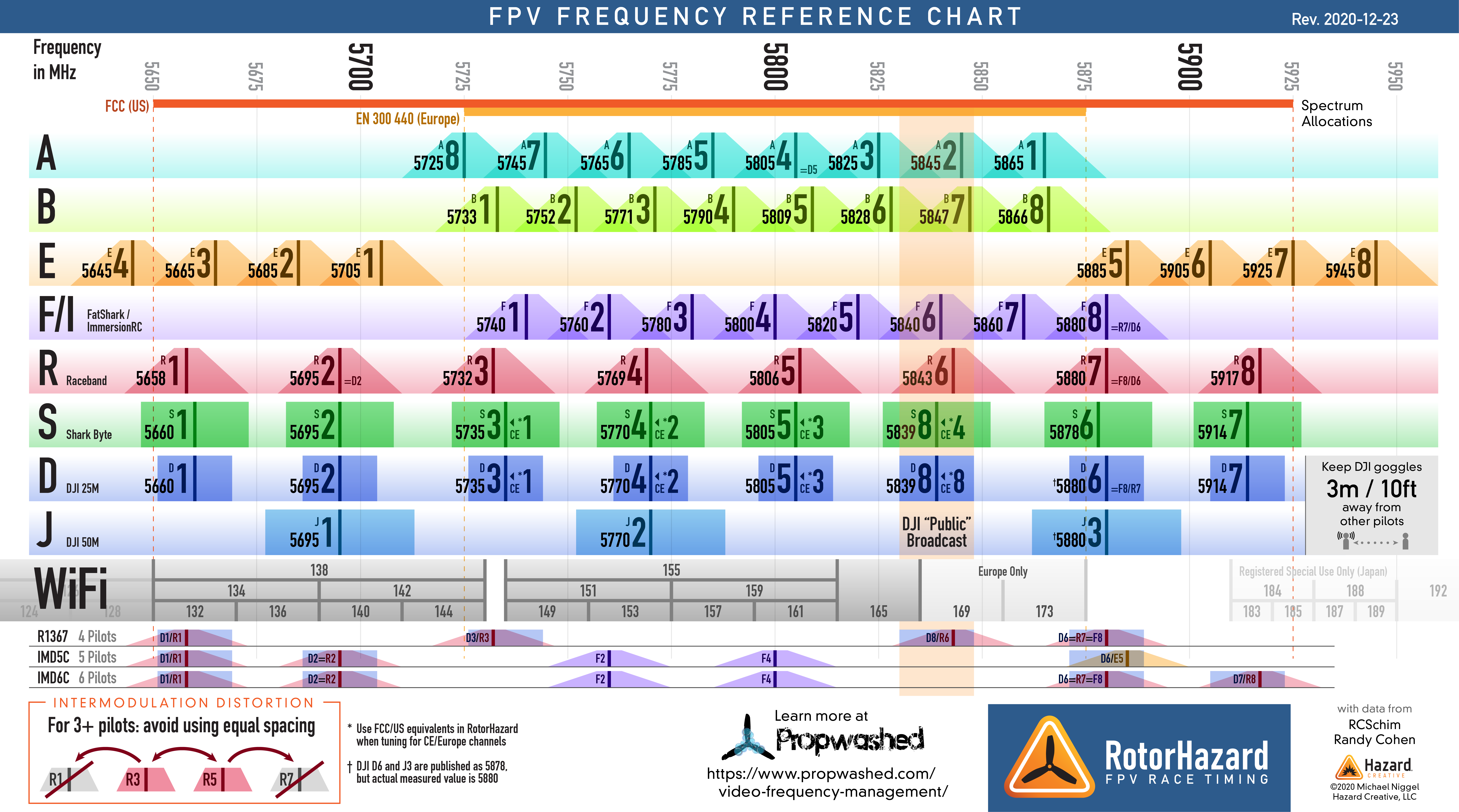
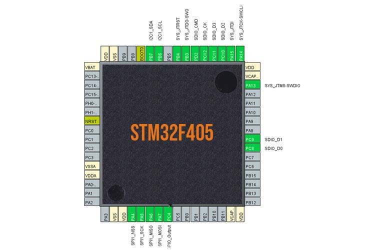